Gigabyte GA-965G-DS4 Manual
Gigabyte GA-965G-DS4 Manual
 |
View all Gigabyte GA-965G-DS4 manuals
Add to My Manuals
Save this manual to your list of manuals |
Gigabyte GA-965G-DS4 manual content summary:
- Gigabyte GA-965G-DS4 | Manual - Page 1
GA-965G-DS4 Intel® CoreTM 2 Extreme quad-core / CoreTM 2 Quad / Intel® CoreTM 2 Extreme dual-core / CoreTM 2 Duo / Intel® Pentium® Processor Extreme Edition / Intel® Pentium® D / Pentium® 4 LGA775 Processor Motherboard User's Manual Rev. 3301 12ME-965GDS4-3301R * The WEEE marking on the product - Gigabyte GA-965G-DS4 | Manual - Page 2
Motherboard GA-965G-DS4 Oct. 18, 2006 Motherboard GA-965G-DS4 Oct. 18, 2006 - Gigabyte GA-965G-DS4 | Manual - Page 3
the product. „ For detailed product information and specifications, please carefully read the "Product User Manual". „ For detailed information related to Gigabyte's unique features, please go to "Technology Guide" section on Gigabyte's website to read or download the information you need. For more - Gigabyte GA-965G-DS4 | Manual - Page 4
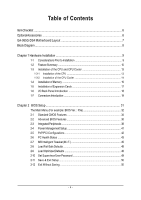
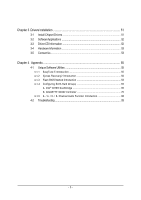
OptionalAccessories ...6 GA-965G-DS4 Motherboard Layout 7 Block Diagram ...8 Chapter 1 Hardware Installation 9 1-1 Considerations Prior to Installation 9 1-2 Feature Summary 10 1-3 Installation of the CPU and CPU Cooler 13 1-3-1 Installation of the CPU 13 1-3-2 Installation of the CPU Cooler - Gigabyte GA-965G-DS4 | Manual - Page 5
5 Introduction 55 4-1-2 Xpress Recovery2 Introduction 56 4-1-3 Flash BIOS Method Introduction 58 4-1-4 Configuring SATA Hard Drive(s 65 A. Intel® ICH8R Southbridge 65 B. GIGABYTE SATA2 Controller 76 4-1-5 2- / 4- / 6- / 8- Channel Audio Function Introduction 88 4-2 Troubleshooting 93 - 5 - - Gigabyte GA-965G-DS4 | Manual - Page 6
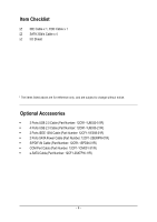
Item Checklist IDE Cable x 1, FDD Cable x 1 SATA 3Gb/s Cable x 4 I/O Shield * The items listed above are for reference only, and are subject to change without notice. Optional Accessories Š 2 Ports USB 2.0 Cable (Part Number: 12CR1-1UB030-51/R) Š 4 Ports USB 2.0 Cable (Part Number: 12CR1- - Gigabyte GA-965G-DS4 | Manual - Page 7
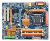
GA-965G-DS4 Motherboard Layout KB_MS COAXIAL OPTICAL ATX_12V_2X LGA775 PWR_FAN PCIE_12V ATX VGA LPT 1394 USB GA-965G-DS4 LAN USB AUDIO BATTERY F_USB1 F_USB2 F_USB3 SATAII4 SATAII1 SATAII2 SATAII5 SATAII3 GIGABYTE SATA2 IDE GSATAII1 GSATAII0 PWR_LED F_PANEL F1_1394 F2_1394 - 7 - Gigabyte GA-965G-DS4 | Manual - Page 8
Channel GIGABYTE SATA2 PCI Bus TSB43AB23 LGA775 Processor CPU CLK +/-(266/200/133 MHz) Host Interface DDRII 800/667/533MHz DIMM(Note) Intel® G965 Dual Channel Memory GMCH CLK (266/200/133 MHz) Intel® ICH8R Dual BIOS motherboard, you must install a 1066/800 MHz FSB processor. - 8 - - Gigabyte GA-965G-DS4 | Manual - Page 9
instructions below: 1. Please turn off the computer and unplug its power cord. 2. When handling the motherboard , avoid touching any metal leads or connectors. 3. It is best to wear an electrostatic discharge (ESD) cuff when handling electronic components (CPU, RAM motherboard problem manual - Gigabyte GA-965G-DS4 | Manual - Page 10
DDRII 800/667/533 unbuffered DIMMs (Note 1) Š Supports 1.8V DDRII DIMMs Š 1 PCI Express x16 slot (the PCIE_16_1 slot) Š 1 PCI Express x4 slot (the PCIE_16_2 slot) Š 3 PCI Express x1 slots (share the same PCIe bus with the PCIE_16_2 slot) (Note 2) Š 2 PCI slots GA-965G-DS4 Motherboard - 10 - - Gigabyte GA-965G-DS4 | Manual - Page 11
/ System temperature detection Š CPU / System / Power fan speed detection Š CPU warning temperature Š CPU / System / Power fan failure warning Š CPU smart fan control BIOS Š 2 8 Mbit flash ROM Š Use of licensed AWARD BIOS Š Supports DualBIOS Š PnP 1.0a, DMI 2.0, SM BIOS 2.3, ACPI 1.0b - 11 - Gigabyte GA-965G-DS4 | Manual - Page 12
. (Note 2) The three PCI Express x1 slots will be unavailable when the PCIE_16_2 slot is in use. (Note 3) EasyTune functions may vary depending on different motherboards. (Note 4) The adjustable range is dependent on CPUs. GA-965G-DS4 Motherboard - 12 - - Gigabyte GA-965G-DS4 | Manual - Page 13
the motherboard supports the CPU. 2. Please take note of the one indented corner of the CPU. If you install the CPU in the wrong direction, the CPU will the frequency beyond the proper specifications, please do so according to your hardware specifications including the CPU, graphics card, memory, - Gigabyte GA-965G-DS4 | Manual - Page 14
the motherboard. The CPU cooler may adhere to the CPU as a result of hardening of the heat paste. To prevent such an occurrence, it is suggested that either thermal tape rather than heat paste be used for heat dissipation or using extreme care when removing the CPU cooler. GA-965G-DS4 Motherboard - Gigabyte GA-965G-DS4 | Manual - Page 15
one direction. If you are unable to insert the module, please switch the direction. The motherboard supports DDR II memory modules, whereby BIOS will automatically detect memory capacity and specifications. Memory modules are designed so that they can be inserted only in one direction. The memory - Gigabyte GA-965G-DS4 | Manual - Page 16
The GA-965G-DS4 includes 4 DIMM sockets, and each Channel has two DIMM sockets as following: Channel 0 : DDRII1, DDRII2 Channel 1 : DDRII3, DDRII4 If you want to operate the Dual Channel Technology, please note the following explanations due to the limitation of Intel chipset specifications. 1. Dual - Gigabyte GA-965G-DS4 | Manual - Page 17
and read the expansion card's installation manual before installing the expansion card in the for the expansion card in system BIOS Setup. 8. Install related driver in the operating system. For left shows to release the card. The motherboard includes a PCIE_12V power connector, which provides extra - Gigabyte GA-965G-DS4 | Manual - Page 18
USB interface. Also make sure your OS supports USB controller. If your OS does not support USB controller, please contact OS vendor for possible patch or driver upgrade. For more information please contact your side speakers can be connected to Side Speaker Out jack. GA-965G-DS4 Motherboard - 18 - - Gigabyte GA-965G-DS4 | Manual - Page 19
English Line In The default Line In jack. Devices like CD-ROM, walkman etc. can be connected to Line In jack. Line Out (Front Speaker Out) The default Line Out (Front Speaker Out) jack. Stereo speakers, earphone or front surround speakers can be connected to Line Out (Front Speaker Out) jack. MIC - Gigabyte GA-965G-DS4 | Manual - Page 20
location on the motherboard and connect tightly. The ATX 12V (2x4) power connector mainly supplies power to the CPU. If the ATX 3 4 5 6 7 8 Definition GND GND GND GND +12V +12V +12V +12V 12 24 1 13 ATX GA-965G-DS4 Motherboard Pin No. 1 2 3 4 5 6 7 8 9 10 11 12 Definition 3.3V 3.3V GND +5V GND - Gigabyte GA-965G-DS4 | Manual - Page 21
a +12V power voltage. The black connector wire is the ground wire (GND). Remember to connect the CPU/system/power fan cable to the CPU_FAN/SYS_FAN/PWR_FAN connector to prevent CPU damage or system hanging caused by overheating. 1 CPU_FAN 1 SYS_FAN CPU_FAN / SYS_FAN : Pin No. Definition 1 GND - Gigabyte GA-965G-DS4 | Manual - Page 22
end of the cable connects to the FDD drive. The types of FDD drives supported are: 360 KB, 720 KB, 1.2 MB, 1.44 MB and 2.88 MB the instructions located on the IDE device). Before attaching the IDE cable, please take note of the foolproof groove in the IDE connector. 1 2 GA-965G-DS4 Motherboard 39 - Gigabyte GA-965G-DS4 | Manual - Page 23
GND RXN RXP GND 10) GSATAII0 / GSATAII1 (SATA 3Gb/s Connector, Controlled by GIGABYTE SATA2) SATA 3Gb/s can provide up to 300 MB/s transfer rate. Please refer to the BIOS setting for the SATA 3Gb/s and install the proper driver in order to work properly. 7 1 Pin No. Definition GSATAII0 1 GND - Gigabyte GA-965G-DS4 | Manual - Page 24
1 MPD+ 1 2 MPD- 3 MPD- 12) BATTERY GA-965G-DS4 Motherboard Danger of explosion if battery is incorrectly replaced. Replace only with the same or equivalent type recommended by the manufacturer. Dispose of used batteries according to the manufacturer's instructions. If you want to erase CMOS - Gigabyte GA-965G-DS4 | Manual - Page 25
English 13) F_PANEL (Front Panel Jumper) Please connect the power LED, PC speaker, reset switch and power switch etc. of your chassis front panel to the F_PANEL connector according to the pin assignment below. Message LED/ Power/ Sleep LED Power Switch Speaker Connector MSG+ MSG- PW+ PWSPEAK+ - Gigabyte GA-965G-DS4 | Manual - Page 26
an AC97 front panel audio module to this connector, please refer to the instructions on page 92 about the software settings. 15) CD_IN (CD IN Connector) Connect CD-ROM or DVD-ROM audio out to the connector. 1 Pin No. Definition 1 CD-L 2 GND 3 GND 4 CD-R GA-965G-DS4 Motherboard - 26 - - Gigabyte GA-965G-DS4 | Manual - Page 27
English 16) SPDIF_IN (S/PDIF In Connector) Use S/PDIF IN feature only when your device has digital output function. Be careful with the polarity of the SPDIF_IN connector. Check the pin assignment carefully while you connect the S/PDIF cable, incorrect connection between the cable and connector - Gigabyte GA-965G-DS4 | Manual - Page 28
. Please contact your nearest dealer for optional COMA cable. Pin No. Definition 1 NDCDA- 2 10 2 NSINA 1 9 3 NSOUTA 4 NDTRA- 5 GND 6 NDSRA- 7 NRTSA- 8 NCTSA- 9 NRIA- 10 No Pin GA-965G-DS4 Motherboard - 28 - - Gigabyte GA-965G-DS4 | Manual - Page 29
Intrusion, Case Open) This 2-pin connector allows your system to detect if the chassis cover is removed. You can check the "Case Opened" status in BIOS Setup. Pin No. Definition 1 1 Signal 2 GND - 29 - Hardware Installation - Gigabyte GA-965G-DS4 | Manual - Page 30
-ACZ_RST VCC3 ACZ_SYNC GND ACZ_SDOUT VCC3 Pin No. 9 10 11 12 13 14 15 16 Definition ACZ_SDIN0 +12V ACZ_SDIN1 No Pin ACZ_SDIN3 3VDUAL ACZ_SDIN2 GND GA-965G-DS4 Motherboard - 30 - - Gigabyte GA-965G-DS4 | Manual - Page 31
BIOS, either Gigabyte's Q-Flash or @BIOS utility can be used. Q-Flash allows the user to quickly and easily update or backup BIOS without entering the operating system. @BIOS is a Windows-based utility that does not require users to boot to DOS before upgrading BIOS but directly download and update - Gigabyte GA-965G-DS4 | Manual - Page 32
in the BIOS Setup when somehow the system is not stable as usual. This action makes the system reset to the default settings for stability. 3. The BIOS Setup menus described in this chapter are for reference only and may differ from the exact settings for your motherboard. GA-965G-DS4 Motherboard - Gigabyte GA-965G-DS4 | Manual - Page 33
setup page includes all the items in standard compatible BIOS. „ Advanced BIOS Features This setup page includes all the items of voltage, fan, speed. „ MB Intelligent Tweaker(M.I.T.) This setup page is control CPU clock and frequency ratio. „ Load Fail-Safe Defaults Fail-Safe Defaults indicates - Gigabyte GA-965G-DS4 | Manual - Page 34
A Floppy 3 Mode Support [1.44M, 3.5"] Manual User can manually BIOS to automatically detect IDE/SATA devices during POST(default) • None Select this if no IDE/SATA devices are used and the system will skip the automatic detection step and allow for faster system start up. GA-965G-DS4 Motherboard - Gigabyte GA-965G-DS4 | Manual - Page 35
inch double-sided drive; 2.88 M byte capacity. Floppy 3 Mode Support (for Japan Area) Disabled Normal Floppy Drive. (Default value) motherboard. Extended Memory The BIOS determines how much extended memory is present during the POST. This is the amount of memory located above 1 MB in the CPU - Gigabyte GA-965G-DS4 | Manual - Page 36
BIOS Features Hard Disk Boot Priority First Boot Device Second Boot Device Third Boot Device Password Check HDD S.M.A.R.T. Capability CPU Priority Select boot sequence for onboard(or add-on cards) SCSI, RAID, etc. Use < > or < > to select a supports this function. GA-965G-DS4 Motherboard - 36 - - Gigabyte GA-965G-DS4 | Manual - Page 37
supported. (Default value) Disabled Disable CPU Hyper Threading. Limit CPUID Max. to 3 (Note) Enabled Limit CPUID Maximum value to 3 when use older OS like NT4. Disabled Disable CPUID Limit for windows wish to see BIOS POST screen, Express VGA card on the motherboard. PCI Set Init Display - Gigabyte GA-965G-DS4 | Manual - Page 38
) Disabled Disable USB 2.0 controller. USB Keyboard Support Enabled Disabled Enable USB keyboard support. Disable USB keyboard support. (Default value) USB Mouse Support Enabled Disabled Enable USB mouse support. Disable USB mouse support. (Default value) GA-965G-DS4 Motherboard - 38 - - Gigabyte GA-965G-DS4 | Manual - Page 39
USB hard drives during POST. Enabled BIOS will scan all USB storage devices : General Help F7: Optimized Defaults This motherboard incorporates cable diagnostic feature designed to detect the attached LAN cable. When a Cable Problem Occurs... If a cable problem occurs on a specified pair of wires - Gigabyte GA-965G-DS4 | Manual - Page 40
Gigabyte SATA2 controller. IDE AHCI RAID/IDE Set the SATA channel to IDE mode. (Default value) Set the SATA channel to AHCI mode. Advanced Host Controller Inteface (AHCI) is an interface specification that allows the storage driver Parallel port as ECP & EPP mode. GA-965G-DS4 Motherboard - 40 - - Gigabyte GA-965G-DS4 | Manual - Page 41
support for High Precision Event Timer (HPET) funtion. (Default value) HPET Mode (Note) 32-bit mode Select 32-bit mode for 32-bit Vista operating system. (Default value) 64-bit mode Select 64-bit mode for 64-bit Vista operating system. (Note) Supported on Vista operating system only. - 41 - BIOS - Gigabyte GA-965G-DS4 | Manual - Page 42
) Set IRQ 3,4,5,7,9,10,11,12,14,15 to PCI 1. Auto assign IRQ to PCI 2. (Default value) Set IRQ 3,4,5,7,9,10,11,12,14,15 to PCI 2. GA-965G-DS4 Motherboard - 42 - - Gigabyte GA-965G-DS4 | Manual - Page 43
CPU temperature at 80oC / 176oF. 90oC / 194oF Monitor CPU temperature at 90oC / 194oF. Disabled Disable this function. (Default value) CPU/SYSTEM/POWER FAN Fail Warning Disabled Disable the fan fail warning function. (Default value) Enabled Enable the fan fail warning function. - 43 - BIOS - Gigabyte GA-965G-DS4 | Manual - Page 44
such CPU fans, selecting PWM will not effectively reduce the fan speed. (Note) Before setting this item to Intel(R) QST, make sure at least DDRII1 or DDRII2 socket in Channel 0 is populated. A small portion of system memory will be shared when Intel® QST is enabled. GA-965G-DS4 Motherboard - 44 - Gigabyte GA-965G-DS4 | Manual - Page 45
Control CPU Voltage Control Normal CPU Vcore [Auto] [18X] [Disabled] 200 [Auto] [Disabled] [Auto] 533 [Option 1] [Manual] [ CPU Host Clock Control. (Default value) Enable CPU Host Clock Control. (Note) This item will show up when you install a processor that supports this function. - 45 - BIOS - Gigabyte GA-965G-DS4 | Manual - Page 46
CPU Intelligent Accelerator 2) is designed to detect CPU loading during software program executing, and automatically adjust CPU computing power to maximize system performance. If you wish to adjust the item manually value) Option 2 DRAM Timing Configuration 2. GA-965G-DS4 Motherboard - 46 - - Gigabyte GA-965G-DS4 | Manual - Page 47
by their requirements. Auto Lets the BIOS configure all system voltage settings. Manual Manually configure the system voltage settings. ~ +0.35V Increase FSB voltrage by 0.05V to 0.35V. CPU Voltage Control Supports adjustable CPU vcore. The adjustable range is dependent on CPUs. (Default value - Gigabyte GA-965G-DS4 | Manual - Page 48
DefaultSs a(vYe/N&)?ENxit Setup PC Health Status Exit Without Saving MB Intelligent Tweaker(M.I.T.) Dual BIOS/Q-Flash Load Optimized Defaults Selecting this field loads the factory defaults for BIOS and Chipset Features which the system automatically detects. GA-965G-DS4 Motherboard - 48 - - Gigabyte GA-965G-DS4 | Manual - Page 49
Set User Password Save & Exit Setup Exit Without Saving Dual BIOS/Q-Flash Change/Set/Disable Password When you select this function, access only basic items. If you select "System" at "Password Check" in Advance BIOS Features Menu, you will be prompted for the password every time the system is - Gigabyte GA-965G-DS4 | Manual - Page 50
Optimized Defaults Set Supervisor Password Set User Password Quit Without Saving (SYa/vNe)?&NExit Setup Exit Without Saving Dual BIOS/Q-Flash Abandon all Data Type "Y" will quit the Setup Utility without saving to RTC CMOS. Type "N" will return to Setup Utility. GA-965G-DS4 Motherboard - 50 - - Gigabyte GA-965G-DS4 | Manual - Page 51
will continue to install other drivers. System will reboot automatically after install the drivers, afterward you can install others application. For USB2.0 driver support under Windows XP operating system, please use Windows Service Pack. After install Windows Service Pack, it will show a question - Gigabyte GA-965G-DS4 | Manual - Page 52
Software Applications This page displays all the tools that Gigabyte developed and some free software, you can choose anyone you want and press "install" to install them. 3-3 Driver CD Information This page lists the contents of software and drivers in this CD-title. GA-965G-DS4 Motherboard - 52 - - Gigabyte GA-965G-DS4 | Manual - Page 53
English 3-4 Hardware Information This page lists all device you have for this motherboard. 3-5 Contact Us Please see the last page for details. - 53 - Drivers Installation - Gigabyte GA-965G-DS4 | Manual - Page 54
English GA-965G-DS4 Motherboard - 54 - - Gigabyte GA-965G-DS4 | Manual - Page 55
support these Unique Software Utilities, please check your MB features.) 4-1-1 EasyTune 5 Introduction EasyTune 5 presents the most convenient Windows Display panel of CPU frequency 8. Function display LEDs Shows the current functions status 9. GIGABYTE Logo Log on to GIGABYTE website 10. Help - Gigabyte GA-965G-DS4 | Manual - Page 56
restoration of hard disk data. Supporting Microsoft operating systems including Windows XP/2000/NT/98/Me BIOS v6.00PG, An Energy Star Ally Copyright (C) 1984-2006, Award Software, Inc. Intel G965 BIOS for 965G-DS4 F5a . . . . : BIOS drivers as well as software. GA-965G-DS4 Motherboard - 56 - - Gigabyte GA-965G-DS4 | Manual - Page 57
Windows 2000, be sure to execute the EnableBigLba.exe program from the driver CD before data backup. 2. It is normal that data backup takes longer time than data restoration. 3. Xpress Recovery2 is compliant with the GPL regulations. 4. On a few motherboards based on Nvidia chipsets, BIOS update - Gigabyte GA-965G-DS4 | Manual - Page 58
Copy Main ROM Data to Backup Load Default Settings Save Settings to CMOS Q-Flash Utility Update Main BIOS from Drive Update Backup BIOS from Drive Save Main BIOS to Drive Save Backup BIOS to Drive PgDn/PgUp: Modify : Move ESC: Reset 1M 1M F10: Power Off GA-965G-DS4 Motherboard - 58 - - Gigabyte GA-965G-DS4 | Manual - Page 59
. Update ESCD failure, checksum error or reset? occurs in the Main BIOS, just BIOS occurs a checksum error or the Main BIOS occurs a WIDE RANGE PROTECTION error and Halt On Error set to Enable, the PC will show messages on the boot screen, and the system will pause and wait for the user's instruction - Gigabyte GA-965G-DS4 | Manual - Page 60
result in system malfunction. Updating the BIOS Step 1: a. In the Dual BIOS / Q-Flash menu, use the UP or DOWN ARROW key to select Update Main BIOS from Drive and press ENTER. If you wish to back up the current BIOS file, use the Save Main BIOS to Drive function. GA-965G-DS4 Motherboard - 60 - - Gigabyte GA-965G-DS4 | Manual - Page 61
press ENTER. Make sure again the BIOS file matches your motherboard model. Step 2: The process of system reading the BIOS file from the floppy disk is displayed on the screen. When the message "Are you sure to update BIOS?" appears, press ENTER. The BIOS update will begin and the current process - Gigabyte GA-965G-DS4 | Manual - Page 62
F11: Save CMOS to BIOS F12: Load CMOS from BIOS Load Optimized Defaults Press Y to load BIOS defaults Step 6: Select Save & Exit Setup and then press Y to save settings to CMOS and exit BIOS Setup. When the system restarts, the whole update process is complete. GA-965G-DS4 Motherboard - 62 - - Gigabyte GA-965G-DS4 | Manual - Page 63
users to update their BIOS under Windows. Just select the desired @BIOS server to download the latest version of BIOS. Fig 1. Installing the @BIOS utility Fig 2. Installation Complete and Run @BIOS Select @BIOS item than click Install Click Start/ Programs/ Gigabyte/ BIOS/ @BIOS Fig 3. The - Gigabyte GA-965G-DS4 | Manual - Page 64
@BIOSTM server, please go onto Gigabyte's web site for downloading and updating it according to method II. IV. Please note that any interruption during updating will cause system unbooted. V. Do not use @BIOS and C.O.M. (Corporate Online Management) at the same time. GA-965G-DS4 Motherboard - 64 - - Gigabyte GA-965G-DS4 | Manual - Page 65
, refer to the connectors introduction section of the user's manual to identify the SATA controller for the connectors. (For example, on the GA-965G-DS4 motherboard, the SATAII0, SATAII1, SATAII2, SATAII3, SATAII4 and SATAII5 connectors are supported by the ICH8R southbridge.) Then connect the power - Gigabyte GA-965G-DS4 | Manual - Page 66
1 ESC: Exit F1: General Help F7: Optimized Defaults The BIOS Setup menus described in this section may not show the exact settings for your motherboard. The actual BIOS Setup menu options you will see shall depend on the motherboard you have and the BIOS version. GA-965G-DS4 Motherboard - 66 - - Gigabyte GA-965G-DS4 | Manual - Page 67
system restarts (Figure 2). CMOS Setup Utility-Copyright (C) 1984-2006 Award Software Advanced BIOS Features Hard Disk Boot Priority First Boot Device Second Boot Device Third Boot Device Password Check HDD S.M.A.R.T. Capability CPU Hyper-Threading Limit CPUID Max. to 3 No-Execute Memory Protect - Gigabyte GA-965G-DS4 | Manual - Page 68
Press CTRL+ I to enter the RAID BIOS setup utility. Intel(R) Matrix Storage Driver Model 0 ST3120026AS 1 ST3120026AS Serial # 3JT354CP 3JT329JX Size Type/Status(Vol ID) 111.7GB Non-RAID Disk 111.7GB Non-RAID Disk [ ]-Select [ESC]-Exit Figure 4 [ENTER]-Select Menu GA-965G-DS4 Motherboard - Gigabyte GA-965G-DS4 | Manual - Page 69
Storage Manager option ROM V6.0.0.1022 ICH8R wRAID5 Copyright(C) 2003-06 Intel Corporation. All Rights Reversed. [ CREATE VOLUME MENU ] Name : RAID Level : Disks : Strip Size : Capacity : RAID_Volume0 RAID0(Stripe) Select Disks 128KB 223.6 GB Create Volume [ HELP ] The following are typical - Gigabyte GA-965G-DS4 | Manual - Page 70
ENTER (Figure 7) to begin the creation of the RAID array. Intel(R) Matrix Storage Manager option ROM V6.0.0.1022 The default value indicates the maximum volume capacity using the selected disks. If less than the maximum capacity is chosen, creation [ENTER]-Select GA-965G-DS4 Motherboard - 70 - - Gigabyte GA-965G-DS4 | Manual - Page 71
RAID Volume 2. Delete RAID Volume 3. Reset Disks to Non-RAID 4. Exit RAID RAID Volume If you want to delete a RAID volume, select the Delete RAID Volume option in Main Menu. Press ENTER and follow on-screen instructions Figure 10 To exit the ICH8R RAID BIOS utility, press ESC in Main Menu. [ENTER - Gigabyte GA-965G-DS4 | Manual - Page 72
the CD-ROM drive folder, double click the MENU.exe file in the BootDrv folder (Figure 13). A command prompt window will open similar to that in Figure 12. Figure 13 (Note 2) For 64-bit Windows Operating System, please select Intel Matrix Storage Manager 64 bit. GA-965G-DS4 Motherboard - 72 - - Gigabyte GA-965G-DS4 | Manual - Page 73
OS installation (Required for AHCI and RAID Mode) Now that you have prepared the SATA driver disk and configured BIOS settings, you are ready to install Windows 2000/XP onto your SATA hard drive with the SATA driver. The following is an example of Windows XP installation. Step 1: Restart your system - Gigabyte GA-965G-DS4 | Manual - Page 74
mass storage devices for use with Windows, press ENTER. S=Specify Additional Device ENTER=Continue F3=Exit Figure 17 (Note) If you set the SATA RAID/AHCI Mode item in BIOS Setup to AHCI mode, please select Intel(R) ICH8R/DO/DH SATA AHCI Controller (Desktop ICH8R). GA-965G-DS4 Motherboard - 74 - - Gigabyte GA-965G-DS4 | Manual - Page 75
using Recovery Console, press R. To quit Setup without installing Windows XP, press F3. Enter= Continue R=Repair F3=Exit Figure 18 (Note: Each time you add a new hard drive to a RAID array, the RAID driver will have to be installed under Windows once for that hard drive. After that, the - Gigabyte GA-965G-DS4 | Manual - Page 76
, refer to the connectors introduction section of the user's manual to identify the SATA controller for the connectors. (For example, on the GA-965G-DS4 motherboard, the GSATAII0 and GSATAII1 connectors are supported by the GIGABYTE SATA2 controller.) Then connect the power connector from your power - Gigabyte GA-965G-DS4 | Manual - Page 77
English Step 2: To boot from Windows installation CD-ROM disk, set First Boot Device under the Advanced BIOS Features menu to CDROM (Figure 2). CMOS Setup Utility-Copyright (C) 1984-2006 Award Software Advanced BIOS Features Hard Disk Boot Priority First Boot Device Second Boot Device Third Boot - Gigabyte GA-965G-DS4 | Manual - Page 78
List ] [ TAB]-Switch Window [ ]-Select ITEM [ENTER]-Action Figure 4 [ESC]-Exit Note: In the main screen, you can select a hard disk in the Hard Disk Drive List block and press ENTER. This allows you to check detailed information about the selected hard disk. GA-965G-DS4 Motherboard - 78 - - Gigabyte GA-965G-DS4 | Manual - Page 79
A. Create Array: In the main screen, press ENTER on the Create RAID Disk Drive item. Then the RAID creation screen appears (Figure 5). GIGABYTE Technology Corp. PCIE-to-SATAII/IDE RAID Controller BIOS V1.06.53 [ Create New RAID ] [ Hard Disk Drive List ] Name: Level: Disks: Block: Size: GRAID_ - Gigabyte GA-965G-DS4 | Manual - Page 80
the RAID capacity. The default value indicates the maximum capacity determined by the selected members. If less than the maximum capacity is chosen, the remaining capacity would be no used. [ ]-Switch Unit [DEL,BS]-Delete Number Figure 8 [ENTER]-Next [ESC]-Abort GA-965G-DS4 Motherboard - 80 - Gigabyte GA-965G-DS4 | Manual - Page 81
to abort. GIGABYTE Technology Corp. PCIE-to-SATAII/IDE RAID Controller BIOS V1.06.53 [ Create New RAID ] [ RAID Inside 120 GB RAID Inside [ RAID Disk Drive List ] Model Name RDD0: GRAID RAID Level 0-Stripe Capacity Status 240 GB Normal Members(HDDx) 01 [ TAB]-Switch Window [ ]-Select RAID - Gigabyte GA-965G-DS4 | Manual - Page 82
120 GB RAID Inside 120 GB RAID Inside [ RAID Disk Drive List ] Model Name RDD0: GRAID Save to Disk & Exit (Y/N)?Y RAID Level 0-Stripe Capacity Status 240 GB Normal Members(HDDx) 01 [ TAB]-Switch Window [ ]-Select ITEM [ENTER]-Action Figure 12 [ESC]-Exit GA-965G-DS4 Motherboard - 82 - Gigabyte GA-965G-DS4 | Manual - Page 83
to mark the selected array (Figure 13). Press Del. GIGABYTE Technology Corp. PCIE-to-SATAII/IDE RAID Controller BIOS V1.06.53 [ Main Menu ] [ Hard Disk Drive List ] Create RAID Disk Drive Delete RAID Disk Drive Revert HDD to Non-RAID Solve Mirror Conflict Rebuild Mirror Drive Save And Exit Setup - Gigabyte GA-965G-DS4 | Manual - Page 84
. From the CD-ROM drive folder, double click the MENU.exe file in the BootDrv folder (Figure 17). A command prompt window will open similar to that in Figure 16. Figure 17 (Note 2) For 64-bit Windows Operating System, please select GIGABYTE SATA-RAID Driver 64Bit. GA-965G-DS4 Motherboard - 84 - - Gigabyte GA-965G-DS4 | Manual - Page 85
OS installation (Required for AHCI and RAID Mode) Now that you have prepared the SATA driver disk and configured BIOS settings, you are ready to install Windows 2000/XP onto your SATA hard drive with the SATA driver. The following is an example of Windows XP installation. Step 1: Restart your system - Gigabyte GA-965G-DS4 | Manual - Page 86
storage devices for use with Windows, press ENTER. S=Specify Additional Device ENTER=Continue F3=Exit Figure 21 (Note) If you set the Onboard SATA/IDE Ctrl Mode item in BIOS Setup to AHCI mode, please select GIGABYTE GBB363 AHCI Controller (Windows 2K/XP/2003). GA-965G-DS4 Motherboard - 86 - - Gigabyte GA-965G-DS4 | Manual - Page 87
Step 5: After the SATA controller driver installation is completed, you can proceed with the Windows XP installation. WindowsXP Professional Setup Welcome to Setup. This port of the Setup program prepares Microsoft(R) Windows (R) XP to run on your computer. To set up Windows XP now, press ENTER. To - Gigabyte GA-965G-DS4 | Manual - Page 88
Following pictures are in Windows XP) Center/Subwoofer Speaker (DACs) that support audio output at up driver, you should find an Audio Manager icon in your system tray (you can also find the icon in Control Panel). Doubleclick the icon to open the Audio Control Panel. GA-965G-DS4 Motherboard - Gigabyte GA-965G-DS4 | Manual - Page 89
a speaker or headphone is plugged into the rear Line Out jack, a small window will pop up and ask you what type of equipment is connected. Choose Headphone completed. 4 Channel Audio Setup STEP 1 : After installation of the audio driver, you should find an Audio Manager icon in your system tray (you - Gigabyte GA-965G-DS4 | Manual - Page 90
. 6 Channel Audio Setup STEP 1 : After installation of the audio driver, you should find an Audio Manager icon in your system tray (you plugging in 6-channel speakers to the rear speaker jacks, a small window will pop up and ask you what type of equipment is connected GA-965G-DS4 Motherboard - 90 - - Gigabyte GA-965G-DS4 | Manual - Page 91
Audio Setup STEP 1 : After installation of the audio driver, you should find an Audio Manager icon in your 8CH Speaker. STEP 3: After plugging in 8-channel speakers to the rear speaker jacks, a small window will pop up and ask you what type of equipment is connected. Choose a device depending on - Gigabyte GA-965G-DS4 | Manual - Page 92
panel audio connector to support AC97 Audio mode, go to the Audio Control Panel and click the Audio I/O tab. In the ANALOG area, click the Tool icon and then select the Disable front panel jack detection check box. This action completes the AC'97 Audio configuration. GA-965G-DS4 Motherboard - 92 - - Gigabyte GA-965G-DS4 | Manual - Page 93
Troubleshooting Below is a collection of general asked questions. To check general asked questions based on a specific motherboard model, please log on to GIGABYTE's website. Question 1: I cannot see some options that were included in previous BIOS after updating BIOS in the manual. If your maximum - Gigabyte GA-965G-DS4 | Manual - Page 94
. 814 Xian TEL: +86-29-85531943 FAX: +86-29-85539821 Shenyang TEL: +86-24-83992901 FAX: +86-24-83992909 y India GIGABYTE TECHNOLOGY (INDIA) LIMITED WEB address : http://www.gigabyte.in y Australia GIGABYTE TECHNOLOGY PTY. LTD. WEB address : http://www.gigabyte.com.au GA-965G-DS4 Motherboard - 94 - - Gigabyte GA-965G-DS4 | Manual - Page 95
BYTE Technology Co., Ltd. in SERBIA & MONTENEGRO WEB address : http://www.gigabyte.co.yu y GIGABYTE Global Service System To submit a technical or non-technical (Sales/ Marketing) question, please link to : http://ggts.gigabyte.com.tw Then select your language to enter the system. - 95 - Appendix - Gigabyte GA-965G-DS4 | Manual - Page 96
English GA-965G-DS4 Motherboard - 96 -
-
 1
1 -
 2
2 -
 3
3 -
 4
4 -
 5
5 -
 6
6 -
 7
7 -
8
-
9
-
10
-
11
-
12
-
13
-
14
-
15
-
16
-
17
-
18
-
19
-
20
-
21
-
22
-
23
-
24
-
25
-
26
-
27
-
28
-
29
-
30
-
31
-
32
-
33
-
34
-
35
-
36
-
37
-
38
-
39
-
40
-
41
-
42
-
43
-
44
-
45
-
46
-
47
-
48
-
49
-
50
-
51
-
52
-
53
-
54
-
55
-
56
-
57
-
58
-
59
-
60
-
61
-
62
-
63
-
64
-
65
-
66
-
67
-
68
-
69
-
70
-
71
-
72
-
73
-
74
-
75
-
76
-
77
-
78
-
79
-
80
-
81
-
82
-
83
-
84
-
85
-
86
-
87
-
88
-
89
-
90
-
91
-
92
-
93
-
94
-
95
-
96
 |
 |

GA-965G-DS4
Intel
®
Core
TM
2 Extreme quad-core / Core
TM
2 Quad /
Intel
®
Core
TM
2 Extreme dual-core / Core
TM
2 Duo /
Intel
®
Pentium
®
Processor Extreme Edition /
Intel
®
Pentium
®
D / Pentium
®
4 LGA775 Processor Motherboard
User's Manual
Rev. 3301
12ME-965GDS4-3301R
*
The WEEE marking on the product indicates this product must not be disposed of with user's other household waste
and must be handed over to a designated collection point for the recycling of waste electrical and electronic equipment!!
*
The WEEE marking applies only in European Union's member states.