Gigabyte GA-9IVDTH User Manual
Gigabyte GA-9IVDTH Manual
 |
View all Gigabyte GA-9IVDTH manuals
Add to My Manuals
Save this manual to your list of manuals |
Gigabyte GA-9IVDTH manual content summary:
- Gigabyte GA-9IVDTH | User Manual - Page 1
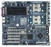
GA-9IVDTH Dual XeonTM (Nocona/Irwindale) Processor Motherboard USER'S MANUAL Name Sign 1. RD 2. BIOS 3. Testing 4. PM Dual XeonTM (Nocona)Processor Motherboard Rev. 1001 - Gigabyte GA-9IVDTH | User Manual - Page 2
Motherboard Table of Content Item Checklist 4 WARNING 4 Chapter 1 Introduction 5 Features Summary 5 GA-9IVDTH Motherboard Layout 7 Chapter 2 Hardware Installation Process 9 Step 1: Install the Central Processing Unit (CPU 10 Step 1-2:CPU Heat Sink Installation 11 Step 2: Install memory - Gigabyte GA-9IVDTH | User Manual - Page 3
English Table of Content Chapter 4 Technical Reference 60 Block Diagram 60 Chapter 5 Driver Installation 61 A.Intel Chipset Driver Installation 61 B.Intel LAN Driver Installation 63 C.Intel Pro Software Utility Installation 64 D.Intel SATA Host Raid Driver Installation 66 E.Adaptec SCSI 7902 - Gigabyte GA-9IVDTH | User Manual - Page 4
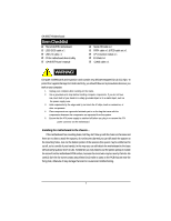
motherboard U320 SCSI cable x 1 USB 2.0 cable x 1 CD for motherboard driver & utility GA-9IVDTH user's manual Serial ATA cable x 2 PATA cable x 1 & FDD cable set x 1 CPU retention module x 1 I/O Shield x1 COM2 cable x 1 WARNING! Computer motherboards and expansion cards contain very delicate - Gigabyte GA-9IVDTH | User Manual - Page 5
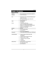
GA-9IVDTH Motherboard: CPU Chipset Memory I/O Control Slots On-Board IDE y Dual socket 604 for Intel® Xeon(Nocona/Irwindale) processor suopprts 3.6 GB and upper y Intel® Xeon (Nocona) CPUs supports Floppy port supports 2 FDD with 720K, 1.44M and 2.88M bytes. y 1 Parallel port supports Normal/EPP/ - Gigabyte GA-9IVDTH | User Manual - Page 6
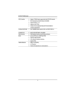
English GA-9IVDTH Motherboard SCSI Controller On-Board SATA RAID y Adaptec® 7902W chipset supports dual ultra 320 SCSI channels y Mirroring supports automatic background rebuilds y Supports RAID 0 ,1, 10 y Supports HOST RAID y Features LBA and Extended Interrupt 13 drive translation in controller - Gigabyte GA-9IVDTH | User Manual - Page 7
Hardware Installation Process GA-9IVDTH Motherboard Layout 18 19 V K 㕳㕨 R 㕴㕥㕠 㖃㖇㕡 㕡 J 15 14 13 SS 1 12 11 10 2 㖇㕿㖂㕡 㖃㖀㕻㕡 I 㖃㕾 Z H N O M 3 G F 㕹㕴㕵㕢 㕡 㕢 㕡 㕺㖀㕥 D L 㖄㖀㕡 E C U 㖅㕦㕤 B 21 - Gigabyte GA-9IVDTH | User Manual - Page 8
English GA-9IVDTH Motherboard A. CPU0 (Install First) 1. WOL1 (Wake O Lan) B. Supports 64bit/66MHz) L. SATA1 (SATA Connector) 12. PCI-X_3 (Supports 64bit/66MHz) M. SATA2 (SATA Connector) 13. PCI_4 (Supports 32bit/33MHz) N. IPMB1 14. PCI_5 (Supports 32bit/33MHz) O. IPMB2 15. PCI_6 (Supports - Gigabyte GA-9IVDTH | User Manual - Page 9
Hardware Installation Process Chapter 2 Hardware Installation Process To set up your computer, you must complete the following steps: Step 1- Install the Central Processing Unit (CPU) Step 2- Install memory modules Step 3- Install expansion cards Step 4- Connect ribbon cables, cabinet wires, and - Gigabyte GA-9IVDTH | User Manual - Page 10
English GA-9IVDTH Motherboard Step 1: Install the Central Processing Unit (CPU) well, it will cause improper installation. Please change the insert orientation. Please make sure the CPU type is supported by the motherboard. 1. Angling the rod to 65-degree maybe feel a kind of tight , and then - Gigabyte GA-9IVDTH | User Manual - Page 11
the CPU fan power cable is plugged in to the CPU fan connector, this completes the installation. Please refer to CPU heat sink user's manual for more detail installation procedure. 1. Heat sink installation kit. 2. Turn the mother bord to the backside. Lock the retention module on the mother board - Gigabyte GA-9IVDTH | User Manual - Page 12
English GA-9IVDTH Motherboard 3. Fasten the heatsink supporting-base onto the CPU socket on the mainboard. 4. Make sure the CPU fan is plugged to the CPU fan connector, than install complete. 12 - Gigabyte GA-9IVDTH | User Manual - Page 13
Step 2: Install memory modules Hardware Installation Process Before installing the processor and heatsink, adhere to the following warning: Please note that the DIMM module can only fit in one direction due to the one notches. Wrong orientation will cause improper installation. Please change the - Gigabyte GA-9IVDTH | User Manual - Page 14
English GA-9IVDTH Motherboard 2-1: DDR DIMM Slot Population Table 2-1: Supported DDR266 DIMM Populations DIMM Dual Rank Single Rank 3 Dual Rank Dual Rank Dual Rank Dual Rank Table 2-2: Supported DDR333 DIMM Populations DIMM Configuration DIMM1 1 Single Rank Empty 1 Dual Rank Empty 2 - Gigabyte GA-9IVDTH | User Manual - Page 15
English GA-9IVDTH Motherboard 1. The DIMM slot has a notch, so the DIMM memory module can only fit in one direction. 2. Insert the DIMM memory module vertically into the - Gigabyte GA-9IVDTH | User Manual - Page 16
Step 3: Install expansion cards Hardware Installation Process 1. Read the related expansion card's instruction document before install the expansion card into the computer. 2. Remove your server's chassis cover, necessary screws and slot bracket from the computer. 3. Press the expansion - Gigabyte GA-9IVDTH | User Manual - Page 17
] ] \ 17 Z GA-9IVDTH Motherboard Step 4: Connect ribbon cables, cabinet wires, and power supply Step 4-1 : I/O Back Panel Introduction [ English 㕡 㕢 㕡 㕢㕥 㖃㖀㕻㕡 㕳㕨 㖄㖀㕡 㕡 㖅㕦㕤 㖃㕾 㕱㖄㖈㕡 㕴㕥㕠 㖃㖇㕡 㕱㕢 㕺㖀㕢 - Gigabyte GA-9IVDTH | User Manual - Page 18
patch or driver upgrade. For more information please contact your OS or device(s) vendors. Z/[/\Parallel Port / Serial Port / VGA Port This connector supports 1 standard COM port and 1 Parallel port. Device like printer can be connected to Parallel port ; mouse and modem etc can be connected to - Gigabyte GA-9IVDTH | User Manual - Page 19
English GA-9IVDTH Motherboard Step 4-2 :Connectors Introduction N R 㕳㕨 㕴㕥㕠 㖃㖇㕡 㕡 M H O 㖃㖀㕻㕡 I 㖃㕾 X L V W D G 㕡 㕢 㕡 㕺㖀㕥 E 㖄㖀㕡 F Q 㖅㕦㕤 㕳㕿㕽㕡 㖅㖃㕲㕡 㕼㖀㖄㕡 㕺㖀㕨 S A B 㕱㖄㖈㕣 P - Gigabyte GA-9IVDTH | User Manual - Page 20
A ) ATX 1 (ATX Power Connector) 㖀㕳㕹㕦 㕴㕥㕠 㖃㖇㕡 㕡 㕳㕿㕽㕡 㕼㖀㖄㕡 㕺㖀㕨 㖅㖃㕲㕡 㖃㖀㕻㕡 㖃㕾 㕺㖀㕥 㕡 㕢 㕡 㖄㖀㕡 㖅㕦㕤 㕹㕴㕵㕢 㕤㕩 㕥㕠 㕹㕦 㕺㖀㕧 㖅㕥㕥 AC power cord should only be connected to your power - Gigabyte GA-9IVDTH | User Manual - Page 21
English GA-9IVDTH Motherboard C ) IDE2 Connector Please connect first harddisk to IDE2. The red stripe of the ribbon cable must be FDD1 (Floppy Connector) Please connect the floppy drive ribbon cables to FDD. It supports 720K,1.44M and 2.88Mbytes floppy disk types. The red stripe of the ribbon - Gigabyte GA-9IVDTH | User Manual - Page 22
Connector Introduction E / F ) SATA1/SATA2 (Serial ATA Connectors) You can connect the Serial ATA device to this connector, it provides you high speed transfer rates (150MB/sec). 㖅㖃㕲㕡 㕳㕿㕽㕡 㕴㕥㕠 㖃㖇㕡 㕡 㕼㖀㖄㕡 㖀㕳㕹㕦 㕺㖀㕨 㖃㖀㕻㕡 㕡 㕢 㕡 - Gigabyte GA-9IVDTH | User Manual - Page 23
English GA-9IVDTH Motherboard J / K ) SCSI1 / SCSI2 (SCSI Connector) 㖃㖀㕻㕡 㕴㕥㕠 㖃㖇㕡 㕡 㖃㕾 㕡 㕢 㕡 㖄㖀㕡 㖅㕦㕤 㕳㕿㕽㕡 㕼㖀㖄㕡 㕺㖀㕨 㖅㖃㕲㕡 㕹㕴㕵㕢 㕤㕩 㕥㕠 㕹㕦 㕺㖀㕧 㖅㕥㕥 SCSI 1 SCSI 2 34 1 - Gigabyte GA-9IVDTH | User Manual - Page 24
English GA-9IVDTH Motherboard M ) COM2 㖃㖀㕻㕡 㕴㕥㕠 㖃㖇㕡 㕡 㖃㕾 㕡 㕢 㕡 㖄㖀㕡 㖅㕦㕤 㕹㕴㕵㕢 mainboard via your network adapter which also supports WOL. 㖃㖀㕻㕡 㕴㕥㕠 㖃㖇㕡 㕡 㖃㕾 - Gigabyte GA-9IVDTH | User Manual - Page 25
English GA-9IVDTH Motherboard O ) WOR1 (Wake on Ring) 㖃㖀㕻㕡 㕴㕥㕠 㖃㖇㕡 㕡 㖃㕾 㕡 㕢 㕡 㖄㖀㕡 abnormal condition or damaged by overheating.The CPU fan connector supports Max. current up to 1A . 㕴㕥㕠 㖃㖇㕡 㖅㖃㕲㕡 - Gigabyte GA-9IVDTH | User Manual - Page 26
Connector Introduction R /S / T) SYS_FAN 1 / 2 / 3 (System Fan Connectors) This connector allows you to link with the cooling fan on the system case to lower the system temperature. These connectors are for system use only. 㖃㖀㕻㕡 SYS_FAN 1 㕴㕥㕠 㖃㖇㕡 㕡 㖃㕾 - Gigabyte GA-9IVDTH | User Manual - Page 27
incorrectly replaced. 㕱㕳 Replace only with the same or equivalent type recommended by the manufacturer. Dispose of used batteries according to the manufacturer's instructions. 㖅㕥㕥 If you want to erase CMOS... 1.Turn OFF the computer and unplug the power cord. 2.Remove the battery, wait for 30 - Gigabyte GA-9IVDTH | User Manual - Page 28
English GA-9IVDTH Motherboard Step 4-3 : Jumper Setting Introduction 9 3 8 1 2 10 㕳㕨 㕴㕥㕠 㖃㖇㕡 㕡 㖀㕳㕹㕦 㖃㖀㕻㕡 㖇㕿㖂㕡 7 㖃㕾 6 4 㕡 㕢 㕡 㖄㖀㕡 㖅㕦㕤 㕳㕿㕽㕡 㕼㖀㖄㕡 㕺㖀㕨 㖅㖃㕲㕡 㕹㕴㕵㕢 㕤㕩 㕥㕠 㕹㕦 - Gigabyte GA-9IVDTH | User Manual - Page 29
Jumper Setting 1 ) JP 1 (Onboard LAN2 Enable Function) 㖃㖀㕻㕡 㕴㕥㕠 㖃㖇㕡 㕡 㖃㕾 㕳㕿㕽㕡 㖅㖃㕲㕡 㕼㖀㖄㕡 㕺㖀㕨 1 1 㕺㖀㕥 㕡 㕢 㕡 㖄㖀㕡 㖅㕦㕤 1-2 close: Enable LAN 2 function (Default) 2-3 close: Disable LAN - Gigabyte GA-9IVDTH | User Manual - Page 30
English GA-9IVDTH Motherboard 3 ) JP3 (Onboard VGA Enable/Disable Function) 㖃㖀㕻㕡 㕴㕥㕠 㖃㖇㕡 㕡 㖃㕾 㕡 㕢 㕡 㖄㖀㕡 㖅㕦㕤 㕳㕿㕽㕡 㖅㖃㕲㕡 㕼㖀㖄㕡 㕺㖀㕨 1 1 1-2 close: Enable VGA function (Default) 2-3 close: - Gigabyte GA-9IVDTH | User Manual - Page 31
Jumper Setting 5 ) JP7 (On board SCSI Enable/Disable Function) 㖅㖃㕲㕡 㕳㕿㕽㕡 㕴㕥㕠 㖃㖇㕡 㕡 㕼㖀㖄㕡 㖀㕳㕹㕦 㕺㖀㕨 㖃㖀㕻㕡 㖃㕾 1 1-2 close: Enable SCSI function (Default) 㕺㖀㕥 1 2-3 close: Disable SCSI function 㕡 㕢 㕡 - Gigabyte GA-9IVDTH | User Manual - Page 32
32 㕹㕦 㖅㕥㕥 㕤㕩 㕺㖀㕧 㕥㕠 㕹㕴㕵㕢 㖄㖀㕡 㕡 㕢 㕡 㕢㕥 㖃㖀㕻㕡 㕡 㖅㕦㕤 㖃㕾 㕱㖄㖈㕡 㕴㕥㕠 㖃㖇㕡 㕱㕢 㕺㖀㕢 㕼㖀㖄㕡 㕳㕿㕽㕡 㖅㖃㕲㕡 㕺㖀㕨 Definition PWR + PWR - 1 Pin No. 1 2 8 ) JP_PWR1 ( Power LED Signal - Gigabyte GA-9IVDTH | User Manual - Page 33
33 㕹㕦 㖅㕥㕥 㕤㕩 㕺㖀㕧 㕥㕠 㕹㕴㕵㕢 㖄㖀㕡 㕡 㕢 㕡 㕢㕥 㖃㖀㕻㕡 㕡 㖅㕦㕤 㖃㕾 㕱㖄㖈㕡 㕴㕥㕠 㖃㖇㕡 㕱㕢 㕺㖀㕢 㕼㖀㖄㕡 㕳㕿㕽㕡 㖅㖃㕲㕡 㕺㖀㕨 Definition RST_BTN+ RST_BTN- 1 Pin No. 1 2 10 ) JP_RST_BTN1 ( Reset - Gigabyte GA-9IVDTH | User Manual - Page 34
GA-9IVDTH Motherboard Chapter 3 BIOS Setup BIOS Setup is an overview of the BIOS Setup Program. The program that allows users to modify the basic system configuration. - Gigabyte GA-9IVDTH | User Manual - Page 35
BIOS Setup GETTINGHELP Main Menu The on-line description of the highlighted setup function is displayed at the bottom of the screen. Status Page Setup Menu / Option Page Setup Menu Press F1 to pop up a small help window that describes the appropriate keys to use and the possible selections for the - Gigabyte GA-9IVDTH | User Manual - Page 36
GA-9IVDTH Motherboard Main Once you enter Phoenix BIOS Setup Utility, the Main Menu (Figure 1) will appear on the screen. Use arrow keys to select among the - Gigabyte GA-9IVDTH | User Manual - Page 37
360K byte capacity 1.2MB, 31/2 in. 31/2 inch AT-type high-density drive; 1.2M byte capacity 720K, 31/2 in. 31/2 inch double-sided drive; 720K byte capacity in the computer. There are two types: auto type, and manual type. Manual type is user-definable; Auto type which will automatically detect HDD - Gigabyte GA-9IVDTH | User Manual - Page 38
GA-9IVDTH Motherboard Multi-Sector Transfer This field displays the information of Multi-Sector Transfer Mode. Disabled: The data transfer from and to the device occurs one sector at a time. Auto: The data transfer from and to the device occurs multiple sectors at a time if the device supports it. - Gigabyte GA-9IVDTH | User Manual - Page 39
BIOS Setup Advanced About This Section: Advanced With this section, allowing user to configure your system for basic operation. User can change the processor options, chipset configuration, PCI configuration and chipset control. PhoenixBIOS Setup Utility Main Advanced Security Server Boot PCI - Gigabyte GA-9IVDTH | User Manual - Page 40
GA-9IVDTH Motherboard PCI Configuration PhoenixBIOS Setup Utility PCI Configuration Embedded Vedio Controller Embedded SCSI RAID Controller Embedded NIC Item Specific Help F1: Help Esc: Exit KL: - Gigabyte GA-9IVDTH | User Manual - Page 41
Embedded NIC (Gbit #1 / 2) BIOS Setup Onboard LAN Control Enabled Enable onboard LAN 1 / 2 device. (Default value) Disabled Disable this function. Option ROM Scan Enabled Enableing this item to initialize device expansion ROM. Disabled Disable this function. (Defualt value) 41 - Gigabyte GA-9IVDTH | User Manual - Page 42
GA-9IVDTH Motherboard Advanced Chipset Control PhoenixBIOS Setup Utility Advanced Chipset Control USB Controller [Enabled] Legacy USB Support [Disabled] Force Compliance Mode [Enabled] PCI-E port A Device 2 [Enabled] 4GB PCI Hole Granularity [128MB] Data Parity Error Recovery [Enabled] - Gigabyte GA-9IVDTH | User Manual - Page 43
BIOS Setup Force Compliance Mode This option allows user to function PCI-E Compliance mode by setting item to desired value. Enabled Enables PCI-E Force Compliance mode. (Default Value) Disabled Disables this function. PCI-E port A Device 2 Force PCI Express v1.0 Compability Mode, this PCI-E - Gigabyte GA-9IVDTH | User Manual - Page 44
GA-9IVDTH Motherboard Wake On LAN This option allow user to determine the action of the system when a LAN wake up occurs. Enabled Enable Wake On LAN. (Default value) Disabled Disable this function. Note: This item must enabled if you're running under Windows operating system. 44 - Gigabyte GA-9IVDTH | User Manual - Page 45
BIOS Setup Advanced Processor Option PhoenixBIOS Setup Utility Advanced Processor Option Item Specific Help Hyper Threading Technology [Enabled] Machine Checking [Enabled] Thermal Management 2 [Disabled] Adjacent Cache Line Prefetch [Enabled] Set Max Ext CPUID = 3 [Disabled] Thermal - Gigabyte GA-9IVDTH | User Manual - Page 46
GA-9IVDTH Motherboard Adjacent Cache Line Prefetch Enabled Processor will fetch both cache lines when it requires data that is not currently inits cache. (Defualt value) Disabled - Gigabyte GA-9IVDTH | User Manual - Page 47
BIOS Setup Peripheral Configuration PhoenixBIOS Setup Utility Peripheral Configuration Item Specific Help Serial Port A [Enabled] Base I/O address/IRQ [3F8/IRQ4] Serial Port B [Enabled] Base I/O address/IRQ [2F8/IRQ3] Parallel Port [Enabled] Mode [Bi-directional] Base I/O addreee [ - Gigabyte GA-9IVDTH | User Manual - Page 48
GA-9IVDTH Motherboard Serial Port B This allows users to configure serial prot B by using Using Parallel port as Enhanced Parallel Port. (Default) Bi-directional Use this setting to support bi-directional transfers on the parallel port. ECP Using Parallel port as Extended Capabilities Port. - Gigabyte GA-9IVDTH | User Manual - Page 49
) Disable the Serial ATA. Native Mode Operation This option allows user to set the native mode for ATA function. Note that certain OS is not supported under Native Mode. Auto Auto detected. (Default value) Serial ATA Set Native mode to Serial ATA. Parallel ATA Set Native mode to Parallel ATA - Gigabyte GA-9IVDTH | User Manual - Page 50
GA-9IVDTH Motherboard Hardware Monitor PhoenixBIOS Setup Utility Hardware Monitor Item Specific Help CPU Temperature 38C/100F SDRAM Socket Temperature 33C/091F PCI Connector Temperature 33C/091F - Gigabyte GA-9IVDTH | User Manual - Page 51
Security Main Advanced Supervisor Password Is: Supervisor Password Is: Set Supervisor Password Set User Password Password On Boot PhoenixBIOS Setup Utility Security Server Boot Clear Clear [Enter] [Enter] [Disabled] BIOS Setup Exit Item Specific Help F1: Help Esc: Exit KL: Select - Gigabyte GA-9IVDTH | User Manual - Page 52
GA-9IVDTH Motherboard Set User Password You can only enter but do not have the right to change the options of the setup menus. When you select - Gigabyte GA-9IVDTH | User Manual - Page 53
BIOS Setup Server PhoenixBIOS Setup Utility Main Advanced Security Server Boot Console Redirection Halt On [Mid] Memory RAS Feature Control [Standard] Clear Mem. ECC Error Info. [Disabled] Fatal Err on port A [Enabled] Exit Item Specific Help F1: Help Esc: Exit KL: Select Item IJ: - Gigabyte GA-9IVDTH | User Manual - Page 54
GA-9IVDTH Motherboard Com Port Address If this option is set to enabled, it will use be set to CTS/RTS or CTS/RTS+CD depending on whether a modem is used. None Not supported. XON/OFF Software control. CTS/RTS Hardware control. (Default values) Continue C.R. after POST This option allows - Gigabyte GA-9IVDTH | User Manual - Page 55
BIOS Setup Halt On The category determines whether the computer will stop if an error is detected during power up. NO Errors The system boot will not stop for any error that may be detected and you will be prompted. All Errors Whenever the BIOS detects a non-fatal error the system will be - Gigabyte GA-9IVDTH | User Manual - Page 56
GA-9IVDTH Motherboard Boot Main Advanced + CD-ROM Drive + Hard Drive Removable Device PhoenixBIOS Setup Utility Security Server Boot Exit Item Specific Help F1: Help Esc: Exit - Gigabyte GA-9IVDTH | User Manual - Page 57
BIOS Setup Exit PhoenixBIOS Setup Utility Main Advanced Security Server Boot Exit Exit Saving Changes Item Specific Help Exit Discarding Changes Load Settup Default Discard Changes Save Changes F1: Help Esc: Exit KL: Select Item IJ: Select Menu + -: Change Values F5: Setup Defaults - Gigabyte GA-9IVDTH | User Manual - Page 58
GA-9IVDTH Motherboard Exit Saving Changes This option allows user to exit system setup with saving the changes. Press on this item to ask for the - Gigabyte GA-9IVDTH | User Manual - Page 59
BIOS Setup Discard Changes This option allows user to load previos values from CMOS for all setup item. When you press on this item, you will get a confirmation dialog box with a message as below: Setup Confirmation Load previous configuration now? [Yes] [No] Save Changes This option - Gigabyte GA-9IVDTH | User Manual - Page 60
GA-9IVDTH Motherboard RCehvaispitoenr H4isTtoercyhnical Reference Block Diagram 60 - Gigabyte GA-9IVDTH | User Manual - Page 61
Driver Installation RCehvaispitoenr H5istDoriyver Installation A. Intel Chipset Driver Installation Insert the driver CD-title that came with your motherboard into your CD-ROM driver, the driver CD-title will auto start and show a series of Setup Wizard dialog boxes. If not, please double click the - Gigabyte GA-9IVDTH | User Manual - Page 62
GA-9IVDTH Motherboard Installation Completed 5. Installation completed, Click "Finish" to restart computer. (5) 62 - Gigabyte GA-9IVDTH | User Manual - Page 63
Driver Installation B. Intel LAN Driver Installation Insert the driver CD-title that came with your motherboard into your CD-ROM driver, the driver CD-title will auto start and show a series of Setup Wizard dialog boxes. If not, please double click the CD-ROM device icon in "My computer", and - Gigabyte GA-9IVDTH | User Manual - Page 64
GA-9IVDTH Motherboard C. Intel Pro Software Utility Installation Insert the driver CD-title that came with your motherboard into your CD-ROM driver, the driver CD-title will auto start and show the installation guide. If not, please double click the CD-ROM device icon in "My computer", and execute - Gigabyte GA-9IVDTH | User Manual - Page 65
Setup Type Driver Installation Ready to Install the Program 5. Select Typical and click "Next". (5) Insallation Complete 6.Click "Install". (6) 7.Click "Finish". (7) 65 - Gigabyte GA-9IVDTH | User Manual - Page 66
GA-9IVDTH Motherboard D. Intel SATA Host Raid Driver Installation Installation Procedures: 1. The CD auto run program starts, Double click on "Intel SATA Host Raid Driver". 2. Select the - Gigabyte GA-9IVDTH | User Manual - Page 67
Driver Installation E. Adaptec SCSI 7902 Driver Installation Installation Procedures: 1. The CD auto run program starts, Double click on "Adaptec SCSI 7902 Driver". 2. Click on WINDOWS folder. 3. Copy all files to the floppy disk. 4. Reboot the system. 5. Insert the floppy disk and press F6 when - Gigabyte GA-9IVDTH | User Manual - Page 68
GA-9IVDTH Motherboard F. Adaptec SCSI Host Raid Driver Installation Installation Procedures: 1. The CD auto run program starts, Double click on "Adaptec SCSI Hostraid Driver". 2. Select the folder - Gigabyte GA-9IVDTH | User Manual - Page 69
the driver CD-title that came with your motherboard into your CD-ROM driver, the driver CD-title will auto start and show the installation guide. If not, please double click the CD-ROM device icon in "My computer", and execute the setup.exe. Installation Procedures: 1. The CD auto run program - Gigabyte GA-9IVDTH | User Manual - Page 70
GA-9IVDTH Motherboard RCehvaispitoenr H6istAoprypendix Acronyms Acronyms Meaning ACPI Advanced Configuration and Power Interface APM Advanced Power Management AGP Accelerated Graphics Port AMR Audio Modem Riser ACR - Gigabyte GA-9IVDTH | User Manual - Page 71
Manufacturer PCI A.G.P. Controller Power-On Self Test Peripheral Component Interconnect Rambus in-line Memory Module Special Circumstance Instructions Single Edge Contact Cartridge Static Random Access Memory Symmetric Multi-Processing System Management Interrupt Universal Serial Bus Voltage - Gigabyte GA-9IVDTH | User Manual - Page 72
GA-9IVDTH Motherboard Technical Support/RMA Sheet Customer/Country: Contact Person: Company: E-mail Add. : Model name/Lot Number: BIOS version: O.S./A.S.: Network AMR / CNR Keyboard Mouse Power supply Other Device Phone No.: PCB revision: Driver/Utility: Problem Description: 72
-
 1
1 -
 2
2 -
 3
3 -
 4
4 -
 5
5 -
 6
6 -
 7
7 -
8
-
9
-
10
-
11
-
12
-
13
-
14
-
15
-
16
-
17
-
18
-
19
-
20
-
21
-
22
-
23
-
24
-
25
-
26
-
27
-
28
-
29
-
30
-
31
-
32
-
33
-
34
-
35
-
36
-
37
-
38
-
39
-
40
-
41
-
42
-
43
-
44
-
45
-
46
-
47
-
48
-
49
-
50
-
51
-
52
-
53
-
54
-
55
-
56
-
57
-
58
-
59
-
60
-
61
-
62
-
63
-
64
-
65
-
66
-
67
-
68
-
69
-
70
-
71
-
72
 |
 |
USER’S MANUAL
GA-9IVDTH
Dual Xeon
TM
(Nocona/Irwindale)
Processor Motherboard
Dual Xeon
TM
(Nocona)Processor Motherboard
Rev. 1001
Name
Sign
1. RD
2. BIOS
3. Testing
4. PM