Gigabyte GA-EP45T-UD3LR Manual
Gigabyte GA-EP45T-UD3LR Manual
 |
UPC - 818313006844
View all Gigabyte GA-EP45T-UD3LR manuals
Add to My Manuals
Save this manual to your list of manuals |
Gigabyte GA-EP45T-UD3LR manual content summary:
- Gigabyte GA-EP45T-UD3LR | Manual - Page 1
GA-EP45T-UD3LR LGA775 socket motherboard for Intel® Core TM processor family/ Intel® Pentium® processor family/Intel® Celeron® processor family User's Manual Rev. 1101 12ME-EP45TU3LR-1101R - Gigabyte GA-EP45T-UD3LR | Manual - Page 2
Motherboard GA-EP45T-UD3LR Oct. 24, 2008 Motherboard GA-EP45T-UD3LR Oct. 24, 2008 - Gigabyte GA-EP45T-UD3LR | Manual - Page 3
with the product. For detailed product information, carefully read the User's Manual. For instructions on how to use GIGABYTE's unique features, read or download the information on/from the Support\Motherboard\Technology Guide page on our website. For product-related information, check on our - Gigabyte GA-EP45T-UD3LR | Manual - Page 4
...6 GA-EP45T-UD3LR Motherboard Layout 7 Block Diagram...8 Chapter 1 Hardware Installation 9 1-1 Installation Precautions 9 1-2 Product Specifications 10 1-3 Installing the CPU and CPU Cooler 13 1-3-1 Installing the CPU 13 1-3-2 Installing the CPU Cooler 15 1-4 Installing the Memory 16 - Gigabyte GA-EP45T-UD3LR | Manual - Page 5
Chipset Drivers 61 3-2 Application Software 62 3-3 Technical Manuals 62 3-4 Contact ...63 3-5 System ...63 3-6 Download Center 64 Chapter 4 Unique Features 65 4-1 Xpress Recovery2 65 4-2 BIOS Update Utilities 70 4-2-1 Updating the BIOS with the Q-Flash Utility 70 4-2-2 Updating the BIOS with - Gigabyte GA-EP45T-UD3LR | Manual - Page 6
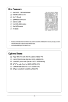
Box Contents GA-EP45T-UD3LR motherboard Motherboard driver disk User's Manual Quick Installation Guide One IDE cable Two SATA 3Gb/s cables One SATA bracket I/O Shield • The box contents above are for reference only and the actual items shall depend - Gigabyte GA-EP45T-UD3LR | Manual - Page 7
GA-EP45T-UD3LR Motherboard Layout KB_MS R_SPDIF R_USB_1 R_USB_2 R_USB_3 USB_LAN ATX_12V PHASE LED CPU_FAN PWR_FAN ATX LGA775 DDR3_1 GA-EP45T-UD3LR DDR3_2 DDR3_3 DDR3_4 FDD SYS_FAN2 F_AUDIO SYS_FAN1 AUDIO Intel® P45 RTL8111C PCIEX1_1 PCIEX1_2 PCIEX16 CODEC SPDIF_O SPDIF_I PCIEX1_3 - Gigabyte GA-EP45T-UD3LR | Manual - Page 8
RTL 8111C x1 PCI Express Bus ATA-133/100/66/ 33 IDE Channel JMicron 368 Host Interface Intel® P45 DDR3 2200/1600/1333/ 1066/800 MHz Dual Channel Memory MCH CLK (400/333/266/200 MHz) Intel® ICH10R Dual BIOS 6 SATA 3Gb/s 12 USB Ports PCI Bus CODEC LPC Bus IT8718 Floppy LPT Port COM Port - Gigabyte GA-EP45T-UD3LR | Manual - Page 9
discharge (ESD) wrist strap when handling electronic components such as a motherboard, CPU or memory. If you do not have an ESD wrist strap, keep your hands are uncertain about any installation steps or have a problem related to the use of the product, please consult a certified computer technician - Gigabyte GA-EP45T-UD3LR | Manual - Page 10
in the LGA 775 package (Go to GIGABYTE's website for the latest CPU support list.) L2 cache varies with CPU 1600/1333/1066/800 MHz FSB North Bridge: Intel® P45 Express Chipset South Bridge: Intel® ICH10R 4 x 1.5V DDR3 DIMM sockets supporting up to 16 GB of system memory (Note 1) Dual - Gigabyte GA-EP45T-UD3LR | Manual - Page 11
Internal Connectors 1 x 24-pin ATX main power connector 1 x 4-pin ATX 12V power connector 1 x floppy disk drive connector 1 x IDE connector 6 x SATA 3Gb/s connectors 1 x CPU fan header 2 x system fan headers 1 x power fan header 1 x front panel header 1 x front panel - Gigabyte GA-EP45T-UD3LR | Manual - Page 12
installed, the actual memory size displayed will be less than 4 GB. (Note 2) Whether the CPU/System fan speed control function is supported will depend on the CPU/ System cooler you install. (Note 3) Available functions in EasyTune may differ by motherboard model. GA-EP45T-UD3LR Motherboard - 12 - - Gigabyte GA-EP45T-UD3LR | Manual - Page 13
do so according to your hardware specifications including the CPU, graphics card, memory, hard drive, etc. 1-3-1 Installing the CPU A. Locate the alignment keys on the motherboard CPU socket and the notches on the CPU. LGA775 CPU Socket Alignment Key LGA 775 CPU Alignment Key Pin One Corner of the - Gigabyte GA-EP45T-UD3LR | Manual - Page 14
one corner of the CPU socket (or you may align the CPU notches with the socket alignment keys) and gently insert the CPU into position. Step 5: Once the CPU is properly inserted, replace the load plate and push the CPU socket lever back into its locked position. GA-EP45T-UD3LR Motherboard - 14 - - Gigabyte GA-EP45T-UD3LR | Manual - Page 15
. Check that the Male and Female push pins are joined closely. (Refer to your CPU cooler installation manual for instructions on installing the cooler.) Step 5: After the installation, check the back of the motherboard. If the push pin is inserted as the picture above, the installation is complete - Gigabyte GA-EP45T-UD3LR | Manual - Page 16
. If you are unable to insert the memory, switch the direction. 1-4-1 Dual Channel Memory Configuration This motherboard provides four DDR3 memory sockets and supports Dual Channel Technology. After the memory is installed, the BIOS will automatically detect the specifications and capacity of - Gigabyte GA-EP45T-UD3LR | Manual - Page 17
. Be sure to install DDR3 DIMMs on this motherboard. Notch DDR3 DIMM A DDR3 memory module has a notch, so it can only fit in one direction. Follow the steps below to correctly install your memory modules in the memory sockets. Step 1: Note the orientation of the memory module. Spread the retaining - Gigabyte GA-EP45T-UD3LR | Manual - Page 18
expansion card: • Make sure the motherboard supports the expansion card. Carefully read the manual that came with your expansion card. necessary, go to BIOS Setup to make any required BIOS changes for your expansion card(s). 7. Install the driver provided with the GA-EP45T-UD3LR Motherboard - 18 - - Gigabyte GA-EP45T-UD3LR | Manual - Page 19
secure the SATA bracket to the chassis back panel with a screw. Step 2: Connect the SATA cable from the bracket to the SATA port on your motherboard. Step 3: Step 4: Connect the power Plug one end of the cable from the bracket SATA signal cable into to the power supply. the external SATA - Gigabyte GA-EP45T-UD3LR | Manual - Page 20
an external audio system that supports digital optical audio. Before external audio system that supports digital coaxial audio. Before connector. USB Port The USB port supports the USB 2.0/1.1 specification. Use this device and then remove it from the motherboard. • When removing the cable, pull - Gigabyte GA-EP45T-UD3LR | Manual - Page 21
to perform different functions via the audio software. Only microphones still MUST be connected to the default Mic in jack ( ). Refer to the instructions on setting up a 2/4/5.1/ 7.1-channel audio configuration in Chapter 5, "Configuring 2/4/5.1/7.1-Channel Audio." - 21 - Hardware Installation - Gigabyte GA-EP45T-UD3LR | Manual - Page 22
5 2 10 6 4 4 19 20 14 13 8 12 17 16 18 15 7 9 11 1) ATX_12V 2) ATX 3) CPU_FAN 4) SYS_FAN1/SYS_FAN2 5) PWR_FAN 6) FDD 7) IDE 8) SATA2_0/1/2/3/4/5 9) PWR_LED 10) F_AUDIO 11) F_PANEL 12) CD_IN been securely attached to the connector on the motherboard. GA-EP45T-UD3LR Motherboard - 22 - - Gigabyte GA-EP45T-UD3LR | Manual - Page 23
ATX (2x2 12V Power Connector and 2x12 Main Power Connector) With the use of the power connector, the power supply can supply enough stable power to all the components on the motherboard . The 12V power connector mainly supplies power to the CPU. If the 12V power connector is not connected, the - Gigabyte GA-EP45T-UD3LR | Manual - Page 24
disk drives supported are: 360 KB, 720 KB, 1.2 MB, 1.44 MB, and 2.88 MB. Before connecting a floppy disk drive, be sure to locate pin 1 of the connector and the floppy disk drive cable. The pin 1 of the cable is typically designated by a stripe of different color. 34 33 GA-EP45T-UD3LR Motherboard - Gigabyte GA-EP45T-UD3LR | Manual - Page 25
with SATA 1.5Gb/s standard. Each SATA connector supports a single SATA device. The ICH10R controller supports RAID 0, RAID 1, RAID 5 and RAID 10. Refer to Chapter 5, "Configuring SATA Hard Drive(s)," for instructions on configuring a RAID array. 7 SATA2_3 SATA2_4 SATA2_5 7 17 17 1 SATA2_0 - Gigabyte GA-EP45T-UD3LR | Manual - Page 26
F_AUDIO (Front Panel Audio Header) The front panel audio header supports Intel High Definition audio (HD) and AC'97 audio. You may audio header supports HD audio by default. If your chassis provides an AC'97 front panel audio module, refer to the instructions on how GA-EP45T-UD3LR Motherboard - 26 - - Gigabyte GA-EP45T-UD3LR | Manual - Page 27
a beep code. One single short beep will be heard if no problem is detected at system startup. If a problem is detected, the BIOS may issue beeps in different patterns to indicate the problem. Refer to Chapter 5, "Troubleshooting," for information about beep codes. • HD (Hard Drive Activity LED, Blue - Gigabyte GA-EP45T-UD3LR | Manual - Page 28
header supports digital S/PDIF in and can connect to an audio device that supports digital audio out via an optional S/PDIF in cable. For purchasing the optional S/PDIF in cable, please contact the local dealer. 1 Pin No. Definition 1 Power 2 SPDIFI 3 GND GA-EP45T-UD3LR Motherboard - 28 - Gigabyte GA-EP45T-UD3LR | Manual - Page 29
supports digital S/PDIF out and connects a S/PDIF digital audio cable (provided by expansion cards) for digital audio output from your motherboard information about connecting the S/PDIF digital audio cable, carefully read the manual for your expansion card. Pin No. Definition 1 SPDIFO 1 2 - Gigabyte GA-EP45T-UD3LR | Manual - Page 30
optional COM port cable, please contact the local dealer. 9 1 10 2 Pin No. 1 2 3 4 5 6 7 8 9 10 Definition NDCD NSIN NSOUT NDTR GND NDSR NRTS NCTS NRI No Pin GA-EP45T-UD3LR Motherboard - 30 - - Gigabyte GA-EP45T-UD3LR | Manual - Page 31
the jumper. Failure to do so may cause damage to the motherboard. • After system restart, go to BIOS Setup to load factory defaults (select Load Optimized Defaults) or manually configure the BIOS settings (refer to Chapter 2, "BIOS Setup," for BIOS configurations). - 31 - Hardware Installation - Gigabyte GA-EP45T-UD3LR | Manual - Page 32
such as BIOS configurations, CPU loading. The higher the CPU loading, the more the number of lighted LEDs. To enable the Phase LED display function, please first enable Dynamic Energy Saver Advanced. Refer to Chapter 4, "Dynamic Energy Saver Advanced," for more details. GA-EP45T-UD3LR Motherboard - Gigabyte GA-EP45T-UD3LR | Manual - Page 33
that searches and downloads the latest version of BIOS from the Internet and updates the BIOS. For instructions on using the Q-Flash and @BIOS utilities, refer to Chapter 4, "BIOS Update Utilities." • Because BIOS flashing is potentially risky, if you do not encounter problems using the current - Gigabyte GA-EP45T-UD3LR | Manual - Page 34
v6.00PG, An Energy Star Ally Copyright (C) 1984-2008, Award Software, Inc. Motherboard Model BIOS Version EP45T-UD3LR E12c . . . . : BIOS Setup : XpressRecovery2 : Boot Menu : Qflash 10/09/2008-P45-ICH10-7A69PG09C-00 Function Keys Function Keys: : POST SCREEN Press the - Gigabyte GA-EP45T-UD3LR | Manual - Page 35
& Exit Setup Exit Without Saving ESC: Quit F8: Q-Flash Select Item F10: Save & Exit Setup F11: Save CMOS to BIOS F12: Load CMOS from BIOS Change CPU's Clock & Voltage BIOS Setup Program Function Keys Move the selection bar to select an item Execute command or enter the submenu - Gigabyte GA-EP45T-UD3LR | Manual - Page 36
and exit BIOS Setup. (Pressing can also carry out this task.) Exit Without Saving Abandon all changes and the previous settings remain in effect. Pressing to the confirmation message will exit BIOS Setup. (Pressing can also carry out this task.) GA-EP45T-UD3LR Motherboard - 36 - Gigabyte GA-EP45T-UD3LR | Manual - Page 37
+/-/PU/PD: Value F10: Save F6: Fail-Safe Defaults ESC: Exit F1: General Help F7: Optimized Defaults (Note 1) This item appears only if you install a CPU that supports this feature. (Note 2) This item appears only if you install a memory module that supports this feature. - 37 - BIOS Setup - Gigabyte GA-EP45T-UD3LR | Manual - Page 38
fails to boot after overclocking, please wait for 20 seconds to allow for automated system reboot, or clear the CMOS values to reset the board to default values. (Default: Disabled) (Note) This item appears only if you install a CPU that supports this feature. GA-EP45T-UD3LR Motherboard - 38 - - Gigabyte GA-EP45T-UD3LR | Manual - Page 39
or 11% depending on CPU loading. Turbo Increases CPU frequency by 15% or 17% depending on CPU loading. Full Thrust Increases CPU frequency by 17% or 19% depending on CPU loading. Warning: Before using C.I.A.2, please first verify the overclocking capability of your CPU. As stability is highly - Gigabyte GA-EP45T-UD3LR | Manual - Page 40
and System Memory Multiplier settings. DRAM Timing Selectable (SPD) Manual allows all DRAM timing control items below to be configurable. Options are: Auto (default), Manual. (Note) This item appears only if you install a memory module that supports this feature. GA-EP45T-UD3LR Motherboard - 40 - Gigabyte GA-EP45T-UD3LR | Manual - Page 41
: Auto (default), 1~255. tRTP Options are: Auto (default), 1~15. Command Rate(CMD) Options are: Auto (default), 1~3. ******** ESC: Exit F1: General Help F7: Optimized Defaults - 41 - BIOS Setup - Gigabyte GA-EP45T-UD3LR | Manual - Page 42
Control Options are: Auto (default), +800ps~-700ps. DIMM2 Clock Skew Control Options are: Auto (default), +800ps~-700ps. ESC: Exit F1: General Help F7: Optimized Defaults GA-EP45T-UD3LR Motherboard - 42 - - Gigabyte GA-EP45T-UD3LR | Manual - Page 43
Disables this function. Enabled Enables this function to enhance memory compatibility. DDR Write Training Allows you to determine whether to fine-tune memory parameters to enhance memory compatibility. Auto Lets the BIOS decide whether to enable this function. (Default) Disabled Disables - Gigabyte GA-EP45T-UD3LR | Manual - Page 44
is Auto. CPU Reference The default is Auto. >>> MCH/ICH MCH Core The default is Auto. MCH Reference The default is Auto. ICH I/O The default is Auto. ICH Core The default is Auto. >>> DRAM DRAM Voltage The default is Auto. DRAM Termination The default is Auto. GA-EP45T-UD3LR Motherboard - 44 - - Gigabyte GA-EP45T-UD3LR | Manual - Page 45
[None] [None] [None] [None] [None] Drive A Floppy 3 Mode Support [1.44M, 3.5"] [Disabled] Halt On [All, But Keyboard] Base Memory Extended Memory Move Enter: Select F5: Previous Values 640K 510M +/-/PU/PD: Value F10: Save devices by using one of the three methods below: - 45 - BIOS Setup - Gigabyte GA-EP45T-UD3LR | Manual - Page 46
manually 3 Mode Support Allows you BIOS POST. Base Memory Also called conventional memory. Typically, 640 KB will be reserved for the MS-DOS operating system. Extended Memory The amount of extended memory. Total Memory The total amount of memory installed on the system. GA-EP45T-UD3LR Motherboard - Gigabyte GA-EP45T-UD3LR | Manual - Page 47
BIOS Features Hard Disk Boot Priority First Boot Device Second Boot Device Third Boot Device Password Check HDD S.M.A.R.T. Capability CPU Multi-Threading (Note) Limit CPUID Max. to 3 (Note) No-Execute Memory Protect (Note) CPU Enhanced Halt (C1E) (Note) C2/C2E State Support on the list. Press < - Gigabyte GA-EP45T-UD3LR | Manual - Page 48
, one computer system can function as multiple virtual systems. (Default: Enabled) (Note) This item is present only if you install a CPU that supports this feature. For more information about Intel CPUs' unique features, please visit Intel's website. GA-EP45T-UD3LR Motherboard - 48 - - Gigabyte GA-EP45T-UD3LR | Manual - Page 49
Allows you to set a delay time for the BIOS to initialize the hard drive as the system boots up. The adjustable range is from 0 to 15 seconds. (Default: 0) Full Screen LOGO Show Allows you to determine whether to display the GIGABYTE Logo at system startup. Disabled displays normal POST message - Gigabyte GA-EP45T-UD3LR | Manual - Page 50
RAID/AHCI Mode (Intel ICH10R Southbridge) Enables or disables RAID for the SATA controllers integrated in the Intel driver to enable advanced Serial ATA features such as Native Command Queuing and hot plug. RAID Enables RAID operating systems that support Native mode. GA-EP45T-UD3LR Motherboard - 50 - - Gigabyte GA-EP45T-UD3LR | Manual - Page 51
LAN Cable Is Attached... If no LAN cable is attached to the motherboard, the Status fields of all four pairs of wires will show Open or when the LAN Boot ROM is activated. When a Cable Problem Occurs... If a cable problem occurs on a specified pair of wires, the Status field will 51 - BIOS Setup - Gigabyte GA-EP45T-UD3LR | Manual - Page 52
. (Default: Disabled) USB Storage Function Determines whether to detect USB storage devices, including USB flash drives and USB hard drives during the POST. (Default: Enabled) GA-EP45T-UD3LR Motherboard - 52 - - Gigabyte GA-EP45T-UD3LR | Manual - Page 53
Support (Note) x HPET Mode Power ON Password AC Back Function EuP Support [S3(STR)] [Instant-Off] [ S3 (Suspend to RAM) sleep state ( , you need an ATX power supply providing at supports wake-up function. (Default: Enabled) (Note) Supported on Windows® Vista® operating system only. - 53 - Gigabyte GA-EP45T-UD3LR | Manual - Page 54
PS/2 keyboard wake-up event. Note: you need an ATX power supply providing at least 1A on the +5VSB lead. Memory The system returns to its last known awake state upon the return of the AC power. EuP Support Supported on Windows® Vista® operating system only. GA-EP45T-UD3LR Motherboard - 54 - - Gigabyte GA-EP45T-UD3LR | Manual - Page 55
IRQ Assignment Auto 3,4,5,7,9,10,11,12,14,15 +/-/PU/PD: Value F10: Save F6: Fail-Safe Defaults ESC: Exit F1: General Help F7: Optimized Defaults BIOS auto-assigns IRQ to the first PCI slot. (Default) Assigns IRQ 3,4,5,7,9,10,11,12,14,15 to the first PCI slot - Gigabyte GA-EP45T-UD3LR | Manual - Page 56
), 60oC/140oF, 70oC/158oF, 80oC/176oF, 90oC/194oF. CPU/SYSTEM/POWER FAN Fail Warning Allows the system to emit warning sound if the CPU/system/power fan is not connected or fails. Check the fan condition or fan connection when this occurs. (Default: Disabled) GA-EP45T-UD3LR Motherboard - 56 - - Gigabyte GA-EP45T-UD3LR | Manual - Page 57
. PWM Sets PWM mode for a 4-pin CPU fan. (Default) Note: The Voltage mode can be set for a 3-pin CPU fan or a 4-pin CPU fan. However, for a 4-pin CPU fan that is not designed following Intel PWM fan specifications, selecting PWM mode may not effectively reduce the fan speed. - 57 - BIOS Setup - Gigabyte GA-EP45T-UD3LR | Manual - Page 58
Press on this item and then press the key to load the optimal BIOS default settings. The BIOS defaults settings helps the system to operate in optimum state. Always load the Optimized defaults after updating the BIOS or after clearing the CMOS values. GA-EP45T-UD3LR Motherboard - 58 - - Gigabyte GA-EP45T-UD3LR | Manual - Page 59
changes. When the Password Check item is set to System, you must enter the supervisor password (or user password) at system startup and when entering BIOS Setup. User Password When the Password Check item is set to System, you must enter the supervisor password (or user password) at system startup - Gigabyte GA-EP45T-UD3LR | Manual - Page 60
F11: Save CMOS to BIOS F12: Load CMOS from BIOS Abandon all Data Press on this item and press the key. This exits the BIOS Setup without saving the changes made in BIOS Setup to the CMOS. Press or to return to the BIOS Setup Main Menu. GA-EP45T-UD3LR Motherboard - 60 - - Gigabyte GA-EP45T-UD3LR | Manual - Page 61
other drivers. • After the drivers are installed, follow the onscreen instructions to restart your system. You can install other applications included in the motherboard driver disk. • For USB 2.0 driver support under the Windows XP operating system, please install the Windows XP Service Pack - Gigabyte GA-EP45T-UD3LR | Manual - Page 62
that GIGABYTE develops and some free software. You can click the Install button on the right of an item to install it. 3-3 Technical Manuals This page provides GIGABYTE's application guides, content descriptions for this driver disk, and the motherboard manuals. GA-EP45T-UD3LR Motherboard - 62 - Gigabyte GA-EP45T-UD3LR | Manual - Page 63
3-4 Contact Click the URL on this page to link to the GIGABYTE Web site. Or read the last page of this manual to check the contact information for GIGABYTE Taiwan headquarter or worldwide branch offices. 3-5 System This page provides the basic system information. - 63 - Drivers Installation - Gigabyte GA-EP45T-UD3LR | Manual - Page 64
3-6 Download Center To update the BIOS, drivers, or applications, click the Download Center button to link to the GIGABYTE Web site. The latest version of the BIOS, drivers, or applications will be displayed. GA-EP45T-UD3LR Motherboard - 64 - - Gigabyte GA-EP45T-UD3LR | Manual - Page 65
system memory • VESA compatible graphics card • Windows® XP with SP1 or later • Xpress Recovery and Xpress Recovery2 are different utilities. For example, a backup file created with Xpress Recovery cannot be restored using Xpress Recovery2. • USB hard drives are not supported. • Hard drives in RAID - Gigabyte GA-EP45T-UD3LR | Manual - Page 66
Drive 1. Set CD-ROM drive as the first boot device under "Advanced BIOS Features" in the BIOS Setup program. Save the changes and exit. 2. When partitioning your hard drive for example, NTFS) and begin the installation of the operating system (Figure 3). Figure 3 GA-EP45T-UD3LR Motherboard - 66 - - Gigabyte GA-EP45T-UD3LR | Manual - Page 67
4. After the operating system is installed, right-click the My Computer icon on your desktop and select Manage (Figure 4). Go to Computer Management to check disk allocation. Xpress Recovery2 will save the backup file to the unallocated space (black stripe along the top)(Figure 5). Please note that - Gigabyte GA-EP45T-UD3LR | Manual - Page 68
from the motherboard driver disk to access Inc. EP45T-UD3LR E12c . . . . : BIOS Setup : XpressRecovery2 : Boot Menu : Qflash 10/09/2008-P45-ICH10-7A69PG09C to check disk allocation. Figure 12 GA-EP45T-UD3LR Motherboard Xpress Recovery2 will automatically create a new partition to - Gigabyte GA-EP45T-UD3LR | Manual - Page 69
D. Using the Restore Function in Xpress Recovery2 Select RESTORE to restore the backup to your hard drive in case the system breaks down. The RESTORE option will not be present if no backup is created before (Figure 13, 14). Figure 13 Figure 14 E. Removing the Backup 1. If you wish to remove the - Gigabyte GA-EP45T-UD3LR | Manual - Page 70
, Inc. EP45T-UD3LR E12c . . . . : BIOS Setup : XpressRecovery2 : Boot Menu : Qflash 10/09/2008-P45-ICH10-7A69PG09C-00 Because BIOS flashing is potentially risky, please do it with caution. Inadequate BIOS flashing may result in system malfunction. GA-EP45T-UD3LR Motherboard - 70 - Gigabyte GA-EP45T-UD3LR | Manual - Page 71
arrow key to select Update BIOS from Drive and press . • The Save Main BIOS to Drive option allows you to save the current BIOS file. • Q-Flash only supports USB flash drive or hard drives using FAT32/16/12 file system. • If the BIOS update file is saved to a hard drive in RAID/AHCI mode or - Gigabyte GA-EP45T-UD3LR | Manual - Page 72
Setup F11: Save CMOS to BIOS F12: Load CMOS from BIOS Load Optimized Defaults Press to load BIOS defaults Step 6: Select Save & Exit Setup and then press to save settings to CMOS and exit BIOS Setup. The procedure is complete after the system restarts. GA-EP45T-UD3LR Motherboard - 72 - - Gigabyte GA-EP45T-UD3LR | Manual - Page 73
location and then download the BIOS file that matches your motherboard model. Follow the on- screen instructions to complete. If the BIOS update file for your motherboard is not present on the @BIOS server site, please manually download the BIOS update file from GIGABYTE's website and follow - Gigabyte GA-EP45T-UD3LR | Manual - Page 74
hardware components such as CPU, chipset, and memory and reduce the useful life of these components. Before you do the overclock/overvoltage, make sure that you fully know each function of EasyTune 6, or system instability or other unexpected results may occur. GA-EP45T-UD3LR Motherboard - 74 - - Gigabyte GA-EP45T-UD3LR | Manual - Page 75
Featuring an advanced proprietary hardware and software design, GIGABYTE Dynamic Energy Saver Advanced is able to provide exceptional Utility Update (Check for the latest utility version) • The above data is for reference only. Actual performance may vary depending on motherboard model. • CPU Power - Gigabyte GA-EP45T-UD3LR | Manual - Page 76
continue to run in taskbar) 15 INFO/Help 16 Live Utility Update (Check for the latest utility version) C. Stealth Mode In Stealth the DES function, make sure the CPU Enhanced Halt (C1E) and CPU EIST Function items in the BIOS Setup program are set to Enabled. . GA-EP45T-UD3LR Motherboard - 76 - - Gigabyte GA-EP45T-UD3LR | Manual - Page 77
for using Q-Share After installing Q-Share from the motherboard driver disk, go to Start>All Programs>GIGABYTE> Q-Share.exe to launch the Q-Share tool. shared data folder Changes the data folder to be shared (Note) Updates Q-Share online Displays the current Q-Share version Exits Q-Share (Note - Gigabyte GA-EP45T-UD3LR | Manual - Page 78
the Microsoft Volume Shadow Copy Services technology, Time Repair allows you to quickly back up and restore your system data in the Windows Vista operating system. Time Repair supports NTFS file system and can only so you cannot edit the contents of a shadow copy. GA-EP45T-UD3LR Motherboard - 78 - - Gigabyte GA-EP45T-UD3LR | Manual - Page 79
BIOS Setup. C . Configure a RAID array in RAID BIOS. (Note 1) D. Make a floppy disk containing the SATA RAID/AHCI driver. (Note 2) E. Install the SATA RAID/AHCI driver RAID, you may prepare only one hard drive. • An empty formatted floppy disk. • Windows Vista/XP setup disk. • Motherboard driver - Gigabyte GA-EP45T-UD3LR | Manual - Page 80
USB Storage Function [RAID] [Disabled] [Auto BIOS Setup. The BIOS Setup menus described in this section may differ from the exact settings for your motherboard. The actual BIOS Setup menu options you will see shall depend on the motherboard you have and the BIOS version. GA-EP45T-UD3LR Motherboard - Gigabyte GA-EP45T-UD3LR | Manual - Page 81
C. Configuring a RAID array in RAID BIOS Enter the RAID BIOS setup utility to configure a RAID array. Skip this step and proceed to the installation of Windows operating system for a non-RAID configuration. Step 1: After the POST memory test begins and before the operating system boot begins, look - Gigabyte GA-EP45T-UD3LR | Manual - Page 82
: RAID Level : Disks : Strip Size : Capacity : Volume0 RAID0(Stripe) Select Disks 128KB 223.6 GB Create Volume [ HELP ] The following are typical values: RAID0 - 128KB RAID10 - 64KB RAID5 - 64KB []-Change [TAB]-Next [ESC]-Previous Menu Figure 5 [ENTER]-Select GA-EP45T-UD3LR Motherboard - Gigabyte GA-EP45T-UD3LR | Manual - Page 83
Disk(0) []-Select [ESC]-Exit Figure 7 [ENTER]-Select Menu To exit the ICH10R RAID BIOS utility, press or select Exit in MAIN MENU. Now, you may proceed to create the SATA RAID/AHCI driver diskette and the installation of the SATA RAID/ACHI driver and operating system. - 83 - Appendix - Gigabyte GA-EP45T-UD3LR | Manual - Page 84
to abort. Intel(R) Matrix Storage Manager option ROM v8.5.0.1013 ICH10R wRAID5 Copyright(C) 2003-08 Intel Corporation. All Rights the disks to non-RAID. WARNING: ALL DISK DATA WILL BE DELETED. []-Select [ESC]-Previous Menu Figure 8 [DEL]-Delete Volume GA-EP45T-UD3LR Motherboard - 84 - - Gigabyte GA-EP45T-UD3LR | Manual - Page 85
copy the SATA controller driver from the motherboard driver disk to your USB flash drive and then extract it (see instructions on the next page). See the instructions below about how to copy the driver in MS-DOS mode(Note). Prepare a startup disk that has CD-ROM support and a blank formatted floppy - Gigabyte GA-EP45T-UD3LR | Manual - Page 86
SATA RAID/AHCI driver diskette and configured the required BIOS support disks from a mass storage device manufacturer, or do not want to specify additional mass storage devices for use with Windows, press ENTER. S=Specify Additional Device ENTER=Continue F3=Exit Figure 2 GA-EP45T-UD3LR Motherboard - Gigabyte GA-EP45T-UD3LR | Manual - Page 87
correct SATA RAID/AHCI driver again from the motherboard driver disk. When the screen as shown below appears, press to continue the driver installation from the floppy disk. The driver installation will be finished in about one minute. Windows Setup Setup will load support for the following - Gigabyte GA-EP45T-UD3LR | Manual - Page 88
Step 4: After the SATA RAID/AHCI driver installation is completed, you can proceed with the Windows XP installation. WindowsXP Professional Setup Welcome to , press R. To quit Setup without installing Windows XP, press F3. Enter= Continue R=Repair F3=Exit Figure 5 GA-EP45T-UD3LR Motherboard - 88 - - Gigabyte GA-EP45T-UD3LR | Manual - Page 89
RAID array exists in your system.) Step 1: Restart your system to boot from the Windows Vista setup disk and perform standard OS installation steps. When a screen similar to that below appears, select Load Driver B to load the driver. Method A: Insert the motherboard driver disk into your system and - Gigabyte GA-EP45T-UD3LR | Manual - Page 90
the RAID/AHCI drive(s) where you want to install the operating system and then press Next to continue the OS installation (Figure 9). Figure 9 (Note) The item displayed in Figure 8 will be shown as Intel(R) ICH10R SATA AHCI Controller when the SATA controllers are set to AHCI mode. GA-EP45T-UD3LR - Gigabyte GA-EP45T-UD3LR | Manual - Page 91
the Audio Control Panel. Before installing the audio driver, make sure the "Microsoft UAA Bus driver for High Definition Audio" has been installed from the motherboard driver disk and your operating system has been updated with the latest Service Pack for Windows. (Note) 2/4/5.1/7.1-Channel Audio - Gigabyte GA-EP45T-UD3LR | Manual - Page 92
Step 2: Click the Audio I/O tab. In the speaker list on the left, select 2CH Speaker, 4CH Speaker, 6CH Speaker, or 8CH Speaker according to the type of Settings box, select the Mute rear panel output when front headphone plugged in check box. Click OK to complete. GA-EP45T-UD3LR Motherboard - 92 - - Gigabyte GA-EP45T-UD3LR | Manual - Page 93
for audio processing. A. Installing the S/PDIF In Cable: Step 1: First, attach the connector at the end of the cable to the SPDIF_I header on your motherboard. Step 2: Secure the metal bracket to the chassis back panel with a screw. - 93 - Appendix - Gigabyte GA-EP45T-UD3LR | Manual - Page 94
) the output source. Click OK to complete the configuration. (Note) The actual locations of the SPDIF In and SPDIF Out connectors may differ by model. GA-EP45T-UD3LR Motherboard - 94 - - Gigabyte GA-EP45T-UD3LR | Manual - Page 95
5-2-3 Configuring Microphone Recording Step 1: After installing the audio driver, the Audio Manager icon will appear in your system tray. Doubleclick the icon to access the Audio Control Panel. Step 2: Connect your microphone to the - Gigabyte GA-EP45T-UD3LR | Manual - Page 96
in Master Volume, go to Options and click Properties. In the Mixer device list, select Realtek HD Audio Input. Then set the recording sound level properly. Do NOT mute the (s) altogether. Select Realtek HD Audio Input in the Mixer device list Recording Control GA-EP45T-UD3LR Motherboard - 96 - - Gigabyte GA-EP45T-UD3LR | Manual - Page 97
Step 6: To raise the recording and playing sound for the microphone, go to Options in Master Volume and select Advanced Controls. Click the Advanced button under a volume control option (e.g. Front Green In, Front Pink In). In the Other Controls field, select the 1 Microphone Boost check box. Step - Gigabyte GA-EP45T-UD3LR | Manual - Page 98
5-3 Troubleshooting 5-3-1 Frequently Asked Questions To read more FAQs for your motherboard, please go to the Support&Downloads\Motherboard\FAQ page on GIGABYTE's website. Q: In the BIOS Setup program, why are some BIOS options missing? A: Some advanced options are hidden in the BIOS Setup program - Gigabyte GA-EP45T-UD3LR | Manual - Page 99
and solved. Secure the CPU No cooler on the CPU. Connect the CPU cooler power cable to the motherboard. The problem is verified and solved. No Correctly insert the memory into the memory socket. The problem is verified and solved. Press to enter BIOS Setup. Select "Load Fail - Gigabyte GA-EP45T-UD3LR | Manual - Page 100
solved. END If the procedure above is unable to solve your problem, contact the place of purchase or local dealer for help. Or go to the Support\Technical Service Zone page to submit your question. Our customer service staff will reply you as soon as possible. GA-EP45T-UD3LR Motherboard - 100 - - Gigabyte GA-EP45T-UD3LR | Manual - Page 101
GIGABYTE. Our Commitment to Preserving the Environment In addition to high-efficiency performance, all GIGABYTE motherboards office, your household waste disposal service or where you purchased the Customer Care number listed in your product's user's manual and we will be glad to help you - Gigabyte GA-EP45T-UD3LR | Manual - Page 102
disposed of properly. China Restriction of Hazardous Substances Table The following table is supplied in compliance with China's Restriction of Hazardous Substances (China RoHS) requirements: GA-EP45T-UD3LR Motherboard - 102 - - Gigabyte GA-EP45T-UD3LR | Manual - Page 103
- 103 - Appendix - Gigabyte GA-EP45T-UD3LR | Manual - Page 104
GA-EP45T-UD3LR Motherboard - 104 - - Gigabyte GA-EP45T-UD3LR | Manual - Page 105
- 105 - Appendix - Gigabyte GA-EP45T-UD3LR | Manual - Page 106
GA-EP45T-UD3LR Motherboard - 106 - - Gigabyte GA-EP45T-UD3LR | Manual - Page 107
- 107 - Appendix - Gigabyte GA-EP45T-UD3LR | Manual - Page 108
GA-EP45T-UD3LR Motherboard - 108 - - Gigabyte GA-EP45T-UD3LR | Manual - Page 109
- 109 - Appendix - Gigabyte GA-EP45T-UD3LR | Manual - Page 110
GA-EP45T-UD3LR Motherboard - 110 - - Gigabyte GA-EP45T-UD3LR | Manual - Page 111
231, Taiwan TEL: +886-2-8912-4000 FAX: +886-2-8912-4003 Tech. and Non-Tech. Support (Sales/Marketing) : http://ggts.gigabyte.com.tw WEB address (English): http://www.gigabyte.com.tw WEB address (Chinese): http://www.gigabyte.tw G.B.T. INC. - U.S.A. TEL: +1-626-854-9338 FAX: +1-626-854-9339 Tech - Gigabyte GA-EP45T-UD3LR | Manual - Page 112
language in the language list on the top right corner of the website. GIGABYTE Global Service System To submit a technical or non-technical (Sales/ Marketing) question, please link to : http://ggts.gigabyte.com.tw Then select your language to enter the system. GA-EP45T-UD3LR Motherboard - 112 -
-
 1
1 -
 2
2 -
 3
3 -
 4
4 -
 5
5 -
 6
6 -
 7
7 -
8
-
9
-
10
-
11
-
12
-
13
-
14
-
15
-
16
-
17
-
18
-
19
-
20
-
21
-
22
-
23
-
24
-
25
-
26
-
27
-
28
-
29
-
30
-
31
-
32
-
33
-
34
-
35
-
36
-
37
-
38
-
39
-
40
-
41
-
42
-
43
-
44
-
45
-
46
-
47
-
48
-
49
-
50
-
51
-
52
-
53
-
54
-
55
-
56
-
57
-
58
-
59
-
60
-
61
-
62
-
63
-
64
-
65
-
66
-
67
-
68
-
69
-
70
-
71
-
72
-
73
-
74
-
75
-
76
-
77
-
78
-
79
-
80
-
81
-
82
-
83
-
84
-
85
-
86
-
87
-
88
-
89
-
90
-
91
-
92
-
93
-
94
-
95
-
96
-
97
-
98
-
99
-
100
-
101
-
102
-
103
-
104
-
105
-
106
-
107
-
108
-
109
-
110
-
111
-
112
 |
 |

GA-EP45T-UD3LR
LGA775 socket motherboard for Intel
®
Core
TM
processor family/
Intel
®
Pentium
®
processor family/Intel
®
Celeron
®
processor family
User's Manual
Rev. 1101
12ME-EP45TU3LR-1101R