Gigabyte GA-G33M-S2 Manual
Gigabyte GA-G33M-S2 Manual
 |
View all Gigabyte GA-G33M-S2 manuals
Add to My Manuals
Save this manual to your list of manuals |
Gigabyte GA-G33M-S2 manual content summary:
- Gigabyte GA-G33M-S2 | Manual - Page 1
GA-G33M-DS2R/ GA-G33M-S2 LGA775 socket motherboard for Intel® CoreTM processor family/ Intel® Pentium® processor family/Intel® Celeron® processor family User's Manual Rev. 1003 12ME-G33MD2R-1003R * The WEEE marking on the product indicates this product must not be disposed of with user's other - Gigabyte GA-G33M-S2 | Manual - Page 2
Motherboard GA-G33M-DS2R Apr. 17, 2007 Motherboard GA-G33M-DS2R Apr. 17, 2007 - Gigabyte GA-G33M-S2 | Manual - Page 3
Motherboard GA-G33M-S2 Apr. 25, 2007 Motherboard GA-G33M-S2 Apr. 25, 2007 - Gigabyte GA-G33M-S2 | Manual - Page 4
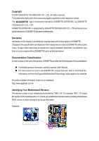
of documentations: „ For detailed product information, carefully read the User's Manual. „ For instructions on how to use GIGABYTE's unique features, read or download the information on/from the Support\Motherboard\Technology Guide page on our website. For product-related information, check on our - Gigabyte GA-G33M-S2 | Manual - Page 5
...7 GA-G33M-DS2R/S2 Motherboard Layout 8 Block Diagram ...9 Chapter 1 Hardware Installation 11 1-1 Installation Precautions 11 1-2 Product Specifications 12 1-3 Installing the CPU and CPU Cooler 15 1-3-1 Installing the CPU 15 1-3-2 Installing the CPU Cooler 17 1-4 Installing the Memory 18 - Gigabyte GA-G33M-S2 | Manual - Page 6
2/4/5.1/7.1-Channel Audio 85 5-2-2 Installing the S/PDIF In and Out Cable (Optional 87 5-2-3 Configuring Microphone Recording 89 5-2-4 Using the Sound Recorder 91 5-3 Troubleshooting 92 5-3-1 Frequently Asked Questions 92 5-3-2 Troubleshooting Procedure 93 Only for GA-G33M-DS2R. - 6 - - Gigabyte GA-G33M-S2 | Manual - Page 7
Box Contents GA-G33M-DS2R or GA-G33M-S2 motherboard Motherboard driver disk User's Manual Intel® LGA775 CPU Installation Guide One IDE cable and one floppy disk drive cable Tow SATA 3Gb/s cables One SATA bracket I/O Shield Only for GA-G33M-DS2R. The box contents above are for reference only and the - Gigabyte GA-G33M-S2 | Manual - Page 8
GA-G33M-DS2R/S2 Motherboard Layout KB_MS ATX_12V LGA775 CPU_FAN IT8718 FDD GA-G33M-DS2R/GA-G33M-S2 DDRII1 COMA LPT VGA USB_1394 SYS _FAN CLR_CMOS USB_LAN AUDIO BATTERY F_AUDIO RTL8111B PCI1 PCI2 CI CD_IN CODEC PCIE_4 SPDIF_IO COMB F1_1394 IDE Intel® G33 PCIE_16 BIOS - Gigabyte GA-G33M-S2 | Manual - Page 9
MHz) BIOS 6 SATA 3Gb/s 4 SATA 3Gb/s 12 USB Ports TSB43AB23 CODEC IT8718 LPT Floppy COM Ports 3 IEEE 1394a Surround Speaker Out Center/Subwoofer Speaker Out Side Speaker Out MIC Line-Out Line-In SPDIF In SPDIF Out 2 PCI PCI CLK(33 MHz) PS/2 KB/Mouse Only for GA-G33M-DS2R. Only for GA-G33M-S2 - Gigabyte GA-G33M-S2 | Manual - Page 10
- 10 - - Gigabyte GA-G33M-S2 | Manual - Page 11
manual and follow these procedures: • Prior to installation, do not remove or break motherboard S/N wrist strap when handling electronic components such as a motherboard, CPU or memory. If you do not have an ESD wrist steps or have a problem related to the use of the product, please consult - Gigabyte GA-G33M-S2 | Manual - Page 12
the LGA 775 package (Go to GIGABYTE's website for the latest CPU support list.) Š Support for Intel® Hyper-Threading Technology Š L2 cache varies with CPU Š 1333/1066/800 MHz FSB Š North Bridge: Intel® G33 Express Chipset Š South Bridge: Intel® ICH9R / ICH9 Š 4 x 1.8V DDR2 DIMM sockets supporting up - Gigabyte GA-G33M-S2 | Manual - Page 13
port Š 4 x USB 2.0/1.1 ports Š 1 x IEEE 1394a port Š 1 x RJ-45 port Š 6 x audio jacks (Center/Subwoofer CPU/System temperature detection Š CPU/System fan speed detection Š CPU overheating warning Š CPU/System fan fail warning Š CPU fan speed control Only for GA-G33M-DS2R. Only for GA-G33M-S2 - Gigabyte GA-G33M-S2 | Manual - Page 14
Chapter 2, "BIOS Setup," "Integrated Peripherals," for details on enabling AHCI.) (Note 3) Available functions in Easytune may differ by motherboard model. (Note 4) Due to chipset limitation, Intel ICH9R RAID driver does not support Windows 2000 operating system. GA-G33M-DS2R/S2 Motherboard - 14 - Gigabyte GA-G33M-S2 | Manual - Page 15
Setup," "Advanced BIOS Features," for instructions on enabling the HT Technology.) 1-3-1 Installing the CPU A. Locate the alignment keys on the motherboard CPU socket and the notches on the CPU. LGA775 CPU Socket Alignment Key LGA 775 CPU Alignment Key Pin One Corner of the CPU Socket Notch - 15 - Gigabyte GA-G33M-S2 | Manual - Page 16
one corner of the CPU socket (or you may align the CPU notches with the socket alignment keys) and gently insert the CPU into position. Step 5: Once the CPU is properly inserted, replace the load plate and push the CPU socket lever back into its locked position. GA-G33M-DS2R/S2 Motherboard - 16 - - Gigabyte GA-G33M-S2 | Manual - Page 17
. Check that the Male and Female push pins are joined closely. (Refer to your CPU cooler installation manual for instructions on installing the cooler.) Step 5: After the installation, check the back of the motherboard. If the push pin is inserted as the picture above, the installation is complete - Gigabyte GA-G33M-S2 | Manual - Page 18
, a message which says memory is operating in Flex Memory Mode will appear during the POST. Intel® Flex Memory Technology offers greater flexibility to upgrade by allowing different memory sizes to be populated and remain in Dual Channel mode/performance. GA-G33M-DS2R/S2 Motherboard - 18 - - Gigabyte GA-G33M-S2 | Manual - Page 19
to install DDR2 DIMMs on this motherboard. Notch DDR2 DIMM A DDR2 memory module has a notch, so it can only fit in one direction. Follow the steps below to correctly install your memory modules in the memory sockets. Step 1: Note the orientation of the memory module. Spread the retaining clips at - Gigabyte GA-G33M-S2 | Manual - Page 20
sure the motherboard supports the expansion card. Carefully read the manual that came with PCI Express x16 slot to release the card and then pull the card straight up from the slot. You can also press the latch on the back of the white-drawable bar to release the card. GA-G33M-DS2R/S2 Motherboard - Gigabyte GA-G33M-S2 | Manual - Page 21
USB Port The USB port supports the USB 2.0/1.1 specification. Use this port for USB devices such as an USB keyboard/mouse, USB printer, USB 100 Mpbs data rate Off 10 Mpbs data rate Activity LED: from your device and then remove it from the motherboard. • When removing the cable, pull it straight - Gigabyte GA-G33M-S2 | Manual - Page 22
perform different functions via the audio software. Only microphones still MUST be connected to the default Mic in jack ( ). Refer to the instructions on setting up a 2/4/5.1/ 7.1-channel audio configuration in Chapter 5, "Configuring 2/4/5.1/7.1-Channel Audio." GA-G33M-DS2R/S2 Motherboard - 22 - - Gigabyte GA-G33M-S2 | Manual - Page 23
11 18 12 13 14 17 16 15 10 8 7 1) ATX_12V 2) ATX (Power Connector) 3) CPU_FAN 4) SYS_FAN 5) FDD 6) IDE 7) SATAII0 / 1 / 2 / 3 / 4 / 5 8) PWR_LED 9) BATTERY 10) F_PANEL 11) F_AUDIO 12) CD_IN 13 attached to the connector on the motherboard. Only for GA-G33M-DS2R. - 23 - Hardware Installation - Gigabyte GA-G33M-S2 | Manual - Page 24
the power connector in the correct orientation. The 12V power connector mainly supplies power to the CPU. If the 12V power connector is not connected, the computer will not start. • To GND GND -5V +5V +5V +5V (Only for 2x12-pin ATX) GND (Only for 2x12-pin ATX) GA-G33M-DS2R/S2 Motherboard - 24 - - Gigabyte GA-G33M-S2 | Manual - Page 25
wire indicates a positive connection and requires a +12V voltage. The black connector wire is the ground wire. The motherboard supports CPU fan speed control, which requires the use of a CPU fan with fan speed control design. For optimum heat dissipation, it is recommended that a system fan be - Gigabyte GA-G33M-S2 | Manual - Page 26
RAID 5 configuration requires at least three hard drives. (The total number of hard drives does not have to be an even number.) • A RAID 10 configuration requires at least four hard drives and the total number of hard drives must be an even number. Only for GA-G33M-DS2R. GA-G33M-DS2R/S2 Motherboard - Gigabyte GA-G33M-S2 | Manual - Page 27
SATA connectors conform to SATA 3Gb/s standard and are compatible with SATA 1.5Gb/s standard. Each SATA connector supports a single SATA device. 7 SATAII4 SATAII5 1 17 71 1 SATAII0 SATAII1 7 Pin No. 1 2 LED S0 On S1 Blinking S3/S4/S5 Off Only for GA-G33M-S2. - 27 - Hardware Installation - Gigabyte GA-G33M-S2 | Manual - Page 28
English 9) BATTERY The battery provides power to keep the values (such as BIOS configurations, date, and time information) in the CMOS when the computer is turned face up). • Used batteries must be handled in accordance with local environmental regulations. GA-G33M-DS2R/S2 Motherboard - 28 - - Gigabyte GA-G33M-S2 | Manual - Page 29
English 10) F_PANEL (Front Panel Header) Connect the power switch, reset will be heard if no problem is detected at system startup. If a problem is detected, the BIOS may issue beeps in different patterns to indicate the problem. Refer to Chapter 5, "Troubleshooting," for information about beep - Gigabyte GA-G33M-S2 | Manual - Page 30
panel audio module that has different wire assignments, please contact the chassis manufacturer. 12) CD_IN (CD In Connector) You may connect the audio cable that came with your optical drive to the header. Pin No. Definition 1 CD-L 1 2 GND 3 GND 4 CD-R GA-G33M-DS2R/S2 Motherboard - 30 - Gigabyte GA-G33M-S2 | Manual - Page 31
GND To enable HDMI, make sure the "Microsoft UAA Bus driver for High Definition Audio" has been installed from the motherboard driver disk and your operating system has been updated with the latest Service Pack for Windows before installing the graphics card driver. - 31 - Hardware Installation - Gigabyte GA-G33M-S2 | Manual - Page 32
cable to your computer and then attach the other end of the cable to the IEEE 1394a device. Ensure that the cable is securely connected. GA-G33M-DS2R/S2 Motherboard - 32 - - Gigabyte GA-G33M-S2 | Manual - Page 33
the optional COM port cable, please contact the local dealer. 2 10 1 9 Pin No. 1 2 3 4 5 6 7 8 9 10 Definition NDCD BNSIN B NSOUT B NDTR BGND NDSR BNRTS BNCTS BNRI BNo Pin 18) CI (Chassis Intrusion Header) This motherboard provides a chassis detection feature that detects if the chassis cover - Gigabyte GA-G33M-S2 | Manual - Page 34
jumper. Failure to do so may cause damage to the motherboard. • After system restart, go to BIOS Setup to load factory defaults (select Load Optimized Defaults) or manually configure the BIOS settings (refer to Chapter 2, "BIOS Setup," for BIOS configurations). GA-G33M-DS2R/S2 Motherboard - 34 - - Gigabyte GA-G33M-S2 | Manual - Page 35
the GIGABYTE Q-Flash or @BIOS utility. • Q-Flash allows the user to quickly and easily upgrade or back up BIOS without entering the operating system. • @BIOS is a Windows-based utility that searches and downloads the latest version of BIOS from the Internet and updates the BIOS. For instructions on - Gigabyte GA-G33M-S2 | Manual - Page 36
the device boot order will still be based on BIOS Setup settings. You can access Boot Menu again to change the first boot device setting as needed. : Q-Flash Press the key to access the Q-Flash utility directly without having to enter BIOS Setup first. GA-G33M-DS2R/S2 Motherboard - 36 - Gigabyte GA-G33M-S2 | Manual - Page 37
> to accept or enter a sub-menu. (Sample BIOS Version: GA-G33M-DS2R D26) CMOS Setup Utility-Copyright (C) 1984-2007 Award Software ` Standard CMOS Features ` Advanced BIOS Features ` Integrated Peripherals ` Power Management Setup ` PnP/PCI Configurations ` PC Health Status ` MB Intelligent Tweaker - Gigabyte GA-G33M-S2 | Manual - Page 38
and exit BIOS Setup. (Pressing can also carry out this task.) „ Exit Without Saving Abandon all changes and the previous settings remain in effect. Pressing to the confirmation message will exit BIOS Setup. (Pressing can also carry out this task.) GA-G33M-DS2R/S2 Motherboard - 38 - Gigabyte GA-G33M-S2 | Manual - Page 39
Mode Support [1.44M, 3.5"] [Disabled] Halt On [All, But Keyboard] Base Memory Extended Memory Total Memory 1664K 511M the three methods below: • Auto Lets BIOS automatically detect IDE/SATA devices during the faster system startup. • Manual Allows you to manually enter the specifications of - Gigabyte GA-G33M-S2 | Manual - Page 40
manually Mode Support Allows you BIOS POST. Base Memory Also called conventional memory. Typically, 640 KB will be reserved for the MS-DOS operating system. Extended Memory The amount of extended memory. Total Memory The total amount of memory installed on the system. GA-G33M-DS2R/S2 Motherboard - Gigabyte GA-G33M-S2 | Manual - Page 41
BIOS Features ` Hard Disk Boot Priority First Boot Device Second Boot Device Third Boot Device Password Check HDD S.M.A.R.T. Capability CPU Hyper-Threading (Note) Limit CPUID Max. to 3 (Note) No-Execute Memory Protect (Note) CPU Enhanced Halt (C1E) (Note) CPU Thermal Monitor 2(TM2) (Note) CPU - Gigabyte GA-G33M-S2 | Manual - Page 42
card as the first display. PEG2 Sets PCI Express x4 graphics card as the first display. (Note) This item is present only if you install a CPU that supports this feature. For more information about Intel CPUs' unique features, please visit Intel's website. GA-G33M-DS2R/S2 Motherboard - 42 - - Gigabyte GA-G33M-S2 | Manual - Page 43
Always activates the onboard VGA, whether or not a PCI Express card is installed. If you wish to set up a dual view configuration, set this item to Always Enable. On-Chip Frame Buffer Size Frame buffer size is the total amount of system memory allocated solely for the onboard graphics controller. MS - Gigabyte GA-G33M-S2 | Manual - Page 44
the storage driver to enable advanced Serial ATA features such as Native Command Queuing and hot plug. For more information about AHCI, please visit Intel's website. Only for GA-G33M-DS2R. Only for GA-G33M-S2. (Note) Supported on Windows® Vista® operating system only. GA-G33M-DS2R/S2 Motherboard - Gigabyte GA-G33M-S2 | Manual - Page 45
mode if you wish to install operating systems that support Native mode, e.g. Windows XP/2000. USB Controller Enables or disables the integrated USB controller. (Default: Enabled) Disabled will turn off all of the USB functionalities below. USB 2.0 Controller Enables or disables the integrated - Gigabyte GA-G33M-S2 | Manual - Page 46
Functioning Normally... If no cable problem is detected on the LAN cable connected to a Gigabit hub or a 10/100 Mbps hub, the 10/100 Mbps environment, so their Status fields will show Open, and the length shown is the approximate length of the attached LAN cable. GA-G33M-DS2R/S2 Motherboard - Gigabyte GA-G33M-S2 | Manual - Page 47
ROM Allows you to decide whether to activate the boot ROM integrated with the onboard LAN chip. (Default: Disabled) Onboard IDE Controller (JMicron 368 Chip) are: SPP (Standard Parallel Port)(default), EPP (Enhanced Parallel Port), ECP (Extended Capabilities Port), ECP+EPP. - 47 - BIOS Setup - Gigabyte GA-G33M-S2 | Manual - Page 48
to enter the ACPI S3 (Suspend to RAM) sleep state (default). In S3 sleep from a PCI or PCIe device. Note: To use this function, you need an ATX power supports wake-up function. (Default: Enabled) (Note) Supported on Windows® Vista® operating system only. GA-G33M-DS2R/S2 Motherboard - 48 - - Gigabyte GA-G33M-S2 | Manual - Page 49
on by a PS/2 keyboard wake-up event. Note: you need an ATX power supply providing at least 1A on the 5VSB lead. Disabled Disables this Memory The system returns to its last known awake state upon the return of the AC power. (Note) Supported on Windows® Vista® operating system only. - 49 - BIOS - Gigabyte GA-G33M-S2 | Manual - Page 50
Help F7: Optimized Defaults BIOS auto-assigns IRQ to the first PCI slot. (Default) Assigns IRQ 3,4,5,7,9,10,11,12,14,15 to the first PCI slot. BIOS auto-assigns IRQ to the second PCI slot. (Default) Assigns IRQ 3,4,5,7,9,10,11,12,14,15 to the second PCI slot. GA-G33M-DS2R/S2 Motherboard - 50 - - Gigabyte GA-G33M-S2 | Manual - Page 51
of previous chassis intrusion status and the Case Opened field will show "No" at next boot. (Default: Disabled) Case Opened Displays the detection status of the chassis intrusion detection device attached to the motherboard CI header. If the system chassis cover is removed, this field will show "Yes - Gigabyte GA-G33M-S2 | Manual - Page 52
, selecting PWM mode may not effectively reduce the fan speed. (Note) Before setting this item to Intel(R) QST, make sure at least DDRII1 or DDRII2 socket in Channel 0 is populated. A small portion of system memory will be shared when Intel® QST is enabled. GA-G33M-DS2R/S2 Motherboard - 52 - - Gigabyte GA-G33M-S2 | Manual - Page 53
: If your system fails to boot after overclocking, please wait for 20 seconds to allow for automated system reboot, or clear the CMOS values to reset the board to default values. (Default: Disabled) (Note) This item appears only if you install a CPU that supports this feature. - 53 - BIOS Setup - Gigabyte GA-G33M-S2 | Manual - Page 54
: Increasing memory voltage may result in damage to the memory. FSB OverVoltage Control Allows you to set the Front Side Bus voltage. Normal Supplies the FSB voltage as required. (Default) +0.1V ~ +0.3V Increases FSB voltage by 0.1V to 0.3V at 0.1V increment. GA-G33M-DS2R/S2 Motherboard - 54 - Gigabyte GA-G33M-S2 | Manual - Page 55
the CPU voltage as required. The adjustable range is dependent on the CPU being installed. (Default: Normal) Note: Increasing CPU voltage may result in damage to your CPU or reduce the useful life of the CPU. Normal CPU Vcore Displays the normal operating voltage of your CPU. - 55 - BIOS Setup - Gigabyte GA-G33M-S2 | Manual - Page 56
Press on this item and then press the key to load the optimal BIOS default settings. The BIOS defaults settings helps the system to operate in optimum state. Always load the Optimized defaults after updating the BIOS or after clearing the CMOS values. GA-G33M-DS2R/S2 Motherboard - 56 - - Gigabyte GA-G33M-S2 | Manual - Page 57
Standard CMOS Features ` Advanced BIOS Features ` Integrated Peripherals ` Power Management Setup ` PnP/PCI ConfigurationEsnter Password: ` PC boot. In BIOS Setup, you must enter the supervisor password if you wish to make changes to BIOS settings. The user password only allows you to view the BIOS - Gigabyte GA-G33M-S2 | Manual - Page 58
` PnP/PCI Configurations Save BIOS F12: Load CMOS from BIOS Abandon all Data Press on this item and press the key. This exits the BIOS Setup without saving the changes made in BIOS Setup to the CMOS. Press or to return to the BIOS Setup Main Menu. GA-G33M-DS2R/S2 Motherboard - Gigabyte GA-G33M-S2 | Manual - Page 59
to restart your system. You can install other applications included in the motherboard driver disk. • For USB 2.0 driver support under the Windows XP operating system, please install the Windows XP Service Pack 1 or later. After installing the SP1 (or later), if a question mark still exists - Gigabyte GA-G33M-S2 | Manual - Page 60
all the tools and applications that GIGABYTE develops and some free software. You may press the Install button following an item to install it. 3-3 Driver CD Information This page provides information about the drivers, applications and tools in this driver disk. GA-G33M-DS2R/S2 Motherboard - 60 - - Gigabyte GA-G33M-S2 | Manual - Page 61
English 3-4 Hardware Information This page provides information about the hardware devices on this motherboard. 3-5 Contact Us Check the contacts information of the GIGABYTE headquarter in Taiwan and the overseas branch offices on the last page of this manual. - 61 - Drivers Installation - Gigabyte GA-G33M-S2 | Manual - Page 62
English GA-G33M-DS2R/S2 Motherboard - 62 - - Gigabyte GA-G33M-S2 | Manual - Page 63
in advanced (10 GB or and drivers are installed. Windows® XP with SP1 or later • Xpress Recovery and Xpress Recovery2 are different utilities. For example, a backup file created with Xpress Recovery cannot be restored using Xpress Recovery2. • USB hard drives are not supported. • Hard drives in RAID - Gigabyte GA-G33M-S2 | Manual - Page 64
Xpress Recovery2 (10 GB or more is recommended; actual size requirements vary, depending on the amount of data) (Figure 2). Figure 1 Figure 2 3. Select a file system (for example, NTFS) and begin the installation of the operating system (Figure 3). Figure 3 GA-G33M-DS2R/S2 Motherboard - 64 - - Gigabyte GA-G33M-S2 | Manual - Page 65
English 4. After the operating system is installed, right-click the My Computer icon on your desktop and select Manage (Figure 4). Go to Computer Management to check disk allocation. Xpress Recovery2 will save the backup file to the unallocated space (black stripe along the top)(Figure 5). Please - Gigabyte GA-G33M-S2 | Manual - Page 66
, Award Software, Inc. Intel G33 BIOS for G33M-DS2R D26 . . . . : BIOS Setup/Q-Flash : XpressRecovery2 : Boot Menu : Qflash 03/30/2007 Figure 10 Figure 11 3. When finished, go to Disk Management to check disk allocation. Figure 12 GA-G33M-DS2R/S2 Motherboard Xpress - Gigabyte GA-G33M-S2 | Manual - Page 67
English D. Using the Restore Function in Xpress Recovery2 Select RESTORE to restore the backup to your hard drive in case the system breaks down. The RESTORE option will not be present if no backup is created before (Figure 13, 14). Figure 13 Figure 14 E. Removing the Backup 1. If you wish to - Gigabyte GA-G33M-S2 | Manual - Page 68
for G33M-DS2R D26 . . . . : BIOS Setup/Q-Flash : XpressRecovery2 : Boot Menu : Qflash 03/30/2007-G33-ICH9R-6A79OG02C-00 Because BIOS flashing is potentially risky, please do it with caution. Inadequate BIOS flashing may result in system malfunction. GA-G33M-DS2R/S2 Motherboard - Gigabyte GA-G33M-S2 | Manual - Page 69
arrow key to select Update BIOS from Drive and press . • The Save Main BIOS to Drive option allows you to save the current BIOS file. • Q-Flash only supports USB flash drive or hard drives using FAT32/16/12 file system. • If the BIOS update file is saved to a hard drive in RAID/AHCI mode or - Gigabyte GA-G33M-S2 | Manual - Page 70
F11: Save CMOS to BIOS F12: Load CMOS from BIOS Load Optimized Defaults Press to load BIOS defaults Step 6: Select Save & Exit Setup and then press to save settings to CMOS and exit BIOS Setup. The procedure is complete after the system restarts. GA-G33M-DS2R/S2 Motherboard - 70 - - Gigabyte GA-G33M-S2 | Manual - Page 71
and Using @BIOS: Use the motherboard driver disk included with the motherboard to install @BIOS. • Installing the @BIOS utility. • Accessing the @BIOS utility. Select @BIOS and click Install. Click Start>Program>Gigabyte>BIOS>@BIOS C. Options and Instructions: 1. Save the Current BIOS File In - Gigabyte GA-G33M-S2 | Manual - Page 72
matches your motherboard model. Updating the BIOS with an incorrect BIOS file could result in an unbootable system. Step 4: As the system boots, press to enter the BIOS Setup program. Select Load Optimized Defaults and press to load BIOS defaults. GA-G33M-DS2R/S2 Motherboard - 72 - Gigabyte GA-G33M-S2 | Manual - Page 73
the BIOS Setup program. EasyTune 5 provides the following functions (Note 1): overclocking/overvoltage, C.I.A./ M.I.B. (Note 2), smart fan control, and hardware monitoring and warning. (For instructions on using EasyTune5, read or download the information on/from the Support\Motherboard\Utility - Gigabyte GA-G33M-S2 | Manual - Page 74
. Click Apply and then OK to activate ReadyBoost function. • The USB flash drive has to have above 256 MB of memory capacity. • The recommend amount of memory to use for ReadyBoost acceleration is one to three times the amount of RAM installed in your computer. GA-G33M-DS2R/S2 Motherboard - 74 - - Gigabyte GA-G33M-S2 | Manual - Page 75
, on this motherboard, the SATAII0, SATAII1, SATAII2, SATAII3, SATAII4 and SATAII5 ports are supported by ICH9R Southbridge.) Then connect the power connector from your power supply to the hard drive. Only for GA-G33M-DS2R. (Note 1) Skip this step if you do not want to create RAID array on the - Gigabyte GA-G33M-S2 | Manual - Page 76
BIOS Setup. The BIOS Setup menus described in this section may differ from the exact settings for your motherboard. The actual BIOS Setup menu options you will see shall depend on the motherboard you have and the BIOS version. Only for GA-G33M-DS2R. Only for GA-G33M-S2. GA-G33M-DS2R/S2 Motherboard - Gigabyte GA-G33M-S2 | Manual - Page 77
C. Configuring a RAID array in RAID BIOS Enter the RAID BIOS setup utility to configure a RAID array. Skip this step and proceed to the installation of Windows operating system for a non-RAID configuration. Step 1: After the POST memory test begins and before the operating system boot begins, look - Gigabyte GA-G33M-S2 | Manual - Page 78
: RAID Level : Disks : Strip Size : Capacity : Volume0 RAID0(Stripe) Select Disks 128KB 223.6 GB Create Volume [ HELP ] The following are typical values: RAID0 - 128KB RAID10 - 64KB RAID5 - 64KB [K L ]-Change [TAB]-Next [ESC]-Previous Menu Figure 5 [ENTER]-Select GA-G33M-DS2R/S2 Motherboard - Gigabyte GA-G33M-S2 | Manual - Page 79
Disk(0) [KL]-Select [ESC]-Exit Figure 7 [ENTER]-Select Menu To exit the ICH9R RAID BIOS utility, press or select Exit in MAIN MENU. Now, you may proceed to create the SATA RAID/AHCI driver diskette and the installation of the SATA RAID/ACHI driver and operating system. - 79 - Appendix - Gigabyte GA-G33M-S2 | Manual - Page 80
] ALL DATA IN THE[VHOELLUPM] E WILL BE LOST! Are you sure you want to delete "Volume0"? (Y/N) : Deleting a volume will reset the disks to non-RAID. WARNING: ALL DISK DATA WILL BE DELETED. [K L ]-Select [ESC]-Previous Menu Figure 8 [DEL]-Delete Volume GA-G33M-DS2R/S2 Motherboard - 80 - - Gigabyte GA-G33M-S2 | Manual - Page 81
be recognized during the Windows setup process. First of all, copy the driver for the SATA controller from the motherboard driver disk to a floppy disk. See the instructions below about how to copy the driver in MS-DOS mode(Note). Prepare a startup disk that has CD-ROM support and a blank formatted - Gigabyte GA-G33M-S2 | Manual - Page 82
manufacturer, press S. * If you do not have any device support disks from a mass storage device manufacturer, or do not want to specify additional mass storage devices for use with Windows, press ENTER. S=Specify Additional Device ENTER=Continue F3=Exit Figure 2 GA-G33M-DS2R/S2 Motherboard - 82 - - Gigabyte GA-G33M-S2 | Manual - Page 83
correct SATA RAID/AHCI driver again from the motherboard driver disk. When the screen as shown below appears, press to continue the driver installation from the floppy disk. The driver installation will be finished in about one minute. Windows Setup Setup will load support for the following - Gigabyte GA-G33M-S2 | Manual - Page 84
Microsoft(R) Windows (R) XP to run on your computer. To set up Windows XP now, press ENTER. To repair a Windows XP installation using Recovery Console, press R. To quit Setup without installing Windows XP, press F3. Enter= Continue R=Repair F3=Exit Figure 5 GA-G33M-DS2R/S2 Motherboard - 84 - Gigabyte GA-G33M-S2 | Manual - Page 85
. Before installing the audio driver, make sure the "Microsoft UAA Bus driver for High Defintion Audio" has been installed from the motherboard driver disk and your operating system has been updated with the latest Service Pack for Windows. (Note) 2/4/5.1/7.1 Channel Audio Configurations: Refer to - Gigabyte GA-G33M-S2 | Manual - Page 86
front panel jack detection check box. Click OK to activiate the AC'97 functionality. When using an AC'97 front panel audio module, you can only have audio signals present on either the front or the back panel audio connections, but not both at the same time. GA-G33M-DS2R/S2 Motherboard - 86 - - Gigabyte GA-G33M-S2 | Manual - Page 87
out cable first if you want to output S/PDIF digital audio signals to an external decoder. A. Installing the S/PDIF In and Out Cable: Step 1: First, attach the connector at the end of the cable to the SPDIF_IO header on your motherboard. Step 2: Secure the metal bracket to the chassis back panel - Gigabyte GA-G33M-S2 | Manual - Page 88
digital audio signals. S/PDIF Optical Cable B. Configuring S/PDIF out: Click the tool icon in the DIGITAL section. In the S/PDIF In/Out Settings dialog box, select an output sampling rate and select (or disable) the output source. Click OK to complete the configuration. GA-G33M-DS2R/S2 Motherboard - Gigabyte GA-G33M-S2 | Manual - Page 89
English 5-2-3 Configuring Microphone Recording Step 1: After installing the audio driver, the Audio Manager icon will appear in your system tray. Double-click the icon to access the Audio Control Panel. Step 2: Connect your microphone to the Mic in jack (pink) on the back panel or the Line in jack - Gigabyte GA-G33M-S2 | Manual - Page 90
list, select Realtek HD Audio Input. Then set the recording sound level properly. Do NOT mute the recording sound, or you will not hear any sound when playing back the recording you just made. Select Realtek HD Audio Input in the Mixer devie list GA-G33M-DS2R/S2 Motherboard Recording Control - 90 - Gigabyte GA-G33M-S2 | Manual - Page 91
, and then click Sound Recorder to begin the sound recording. 5-2-4 Using the Sound Recorder Recording the Sound: 1. Make sure you have connected the audio input device (e.g. microphone) to the computer. 2. On the File menu, choose New. 3. To record a sound file, click the Recording but- ton . 4. To - Gigabyte GA-G33M-S2 | Manual - Page 92
error 1 long, 1 short: Memory or motherboard error 1 long, 2 short: Monitor or graphics card error 1 long, 3 short: Keyboard error 1 long, 9 short: BIOS ROM error Continuous long beeps: Graphics card not inserted properly Continuous short beeps: Power error GA-G33M-DS2R/S2 Motherboard - 92 - - Gigabyte GA-G33M-S2 | Manual - Page 93
and solved. Secure the CPU No cooler on the CPU. Connect the CPU cooler power cable to the motherboard. The problem is verified and solved. No Correctly insert the memory into the memory socket. The problem is verified and solved. Press to enter BIOS Setup. Select "Load Fail - Gigabyte GA-G33M-S2 | Manual - Page 94
solved. END If the procedure above is unable to solve your problem, contact the place of purchase or local dealer for help. Or go to the Support\Technical Service Zone page to submit your question. Our customer service staff will reply you as soon as possible. GA-G33M-DS2R/S2 Motherboard - 94 - - Gigabyte GA-G33M-S2 | Manual - Page 95
Tech. Support (Sales/Marketing) : http://ggts.gigabyte.com.tw WEB address (English): http://www.gigabyte.com.tw WEB address (Chinese): http://www.gigabyte.tw GIGABYTE Global Service System To submit a technical or non-technical (Sales/Marketing) question, please link to : http://ggts.gigabyte. - Gigabyte GA-G33M-S2 | Manual - Page 96
- 96 -
-
 1
1 -
 2
2 -
 3
3 -
 4
4 -
 5
5 -
 6
6 -
 7
7 -
8
-
9
-
10
-
11
-
12
-
13
-
14
-
15
-
16
-
17
-
18
-
19
-
20
-
21
-
22
-
23
-
24
-
25
-
26
-
27
-
28
-
29
-
30
-
31
-
32
-
33
-
34
-
35
-
36
-
37
-
38
-
39
-
40
-
41
-
42
-
43
-
44
-
45
-
46
-
47
-
48
-
49
-
50
-
51
-
52
-
53
-
54
-
55
-
56
-
57
-
58
-
59
-
60
-
61
-
62
-
63
-
64
-
65
-
66
-
67
-
68
-
69
-
70
-
71
-
72
-
73
-
74
-
75
-
76
-
77
-
78
-
79
-
80
-
81
-
82
-
83
-
84
-
85
-
86
-
87
-
88
-
89
-
90
-
91
-
92
-
93
-
94
-
95
-
96
 |
 |

GA-G33M-DS2R/
GA-G33M-S2
LGA775 socket motherboard for Intel
®
Core
TM
processor family/
Intel
®
Pentium
®
processor family/Intel
®
Celeron
®
processor family
User's Manual
Rev. 100
3
12ME-G33MD2R-100
3
R
*
The WEEE marking on the product indicates this product must not be disposed of with user's other household waste
and must be handed over to a designated collection point for the recycling of waste electrical and electronic equipment!!
*
The WEEE marking applies only in European Union's member states.