Gigabyte GA-G33M-S2 Manual - Page 27

PWR_LED System Power LED Header, SATAII0/1/2/4/5 SATA 3Gb/s Connectors, Controlled by ICH9
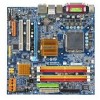
Page 27 highlights

English 7) SATAII0/1/2/4/5 (SATA 3Gb/s Connectors, Controlled by ICH9) The SATA connectors conform to SATA 3Gb/s standard and are compatible with SATA 1.5Gb/s standard. Each SATA connector supports a single SATA device. 7 SATAII4 SATAII5 1 17 71 1 SATAII0 SATAII1 7 Pin No. 1 2 3 4 5 6 7 Definition GND TXP TXN GND RXN RXP GND 8) PWR_LED (System Power LED Header) This header can be used to connect a system power LED on the chassis to indicate system power status. The LED is on when the system is operating. The LED keeps blinking when the system is in S1 sleep state. The LED is off when the system is in S3/S4 sleep state or powered off (S5). Pin No. Definition 1 MPD+ 2 MPD- 1 3 MPD- System Status LED S0 On S1 Blinking S3/S4/S5 Off Only for GA-G33M-S2. - 27 - Hardware Installation

  • 1
  • 2
  • 3
  • 4
  • 5
  • 6
  • 7
  • 8
  • 9
  • 10
  • 11
  • 12
  • 13
  • 14
  • 15
  • 16
  • 17
  • 18
  • 19
  • 20
  • 21
  • 22
  • 23
  • 24
  • 25
  • 26
  • 27
  • 28
  • 29
  • 30
  • 31
  • 32
  • 33
  • 34
  • 35
  • 36
  • 37
  • 38
  • 39
  • 40
  • 41
  • 42
  • 43
  • 44
  • 45
  • 46
  • 47
  • 48
  • 49
  • 50
  • 51
  • 52
  • 53
  • 54
  • 55
  • 56
  • 57
  • 58
  • 59
  • 60
  • 61
  • 62
  • 63
  • 64
  • 65
  • 66
  • 67
  • 68
  • 69
  • 70
  • 71
  • 72
  • 73
  • 74
  • 75
  • 76
  • 77
  • 78
  • 79
  • 80
  • 81
  • 82
  • 83
  • 84
  • 85
  • 86
  • 87
  • 88
  • 89
  • 90
  • 91
  • 92
  • 93
  • 94
  • 95
  • 96

Hardware Installation
- 27 -
English
8)
PWR_LED (System Power LED Header)
This header can be used to connect a system power LED on the chassis to indicate system power
status. The LED is on when the system is operating. The LED keeps blinking when the system is
in S1 sleep state. The LED is off when the system is in S3/S4 sleep state or powered off (S5).
Pin No.
Definition
1
MPD+
2
MPD-
3
MPD-
System Status
LED
S0
On
S1
Blinking
S3/S4/S5
Off
7)
SATAII0/1/2/4/5 (SATA 3Gb/s Connectors, Controlled by ICH9)
The SATA connectors conform to SATA 3Gb/s standard and are compatible with SATA 1.5Gb/s
standard. Each SATA connector supports a single SATA device.
Pin No.
Definition
1
GND
2
TXP
3
TXN
4
GND
5
RXN
6
RXP
7
GND
Only for GA-G33M-S2.
1
SATAII4
SATAII5
SATAII0
7
1
1
7
7
1
1
7
SATAII1