Gigabyte GA-H110M-S2 DDR3 User Manual - Page 17
F_USB1/F_USB2 USB 2.0/1.1 Headers, F_USB30 USB 3.0/2.0 Header, TPM Trusted Platform Module Header
 |
View all Gigabyte GA-H110M-S2 DDR3 manuals
Add to My Manuals
Save this manual to your list of manuals |
Page 17 highlights
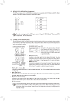
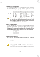
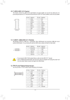
F_USB30 F_ U F_ 10) F_USB30 (USB 3.0/2.0 Header) The header conforms to USB 3.0/2.0 specification and each header can provide two USB ports. For purchasing the optional 3.5" front panel that provides two USB 3.0/2.0 ports, please contact the local dealer. Pin No. Definition Pin No. Definition 20 1 1 VBUS 2 SSRX1- 11 D2+ 12 D2- 3 SSRX1+ 13 GND 4 GND B_ 5 SSTX1- 14 SSTX2+ 1B5S S SSTX2- 6 SSTX1+ 16 1 GND 11 10 7 GND 8 D1- 17 SSRX2+ _S 18 SSRX2- 9 D1+ 19 VBUS 10 NC 20 No Pin S 1 23 1 1 23 1 1 23 1 11) F_USB1/F_USB2 (USB 2.0/1.1 Headers) The headers conform to USB 2.0/1.1 specification. Each USB 1h2e3ader can provide two USB ports via an optional USB bracket. For purchasSing the optional USB bracket, please contact the local dealer. 9 1 10 2 Pin No. 1 2 3 4 5 Definition Power (5V) Power (5V) USB DXUSB DYUSB DX+ Pin No. 6 7 8 9 10 Definition USB DY+ GND GND No Pin NC G.QBOFM S •• Do not plug the IEEE 1394 bracket ••3Prior to installing the USBBSbSrackeSt, (2x5-pin) cable into the be sure to turn off your cUUoSmBp2u.t0e/r1a.1ndheuandpelur.g _the_ pow3er cord from the power outlet to prevent damage to the USB bracket. 12) TPM (Trusted Platform Module Header) S _ You may connect a TPM (Trusted Platform Module) to this header. SF _ Pin No. Definition Pin No. Definition 19 1 1 LCLK 11 LAD0 2 GND 12 GND 20 2 3 LFRAME 13 NC 4 No Pin 14 NC B_5 LRESET 15 _ SB3V DEBUG PORT 6 NC 7 LAD3 16 SERIRQ 17 GND 8 LAD2 18 NC 9 VCC3 19 NC S_ 10 LAD1 20 SUSCLK - 17 - _ _B F_ S F_USB
-
 1
1 -
2
-
3
-
4
-
5
-
6
-
7
-
8
-
9
-
10
-
11
-
 12
12 -
 13
13 -
 14
14 -
 15
15 -
 16
16 -
 17
17 -
 18
18 -
 19
19 -
 20
20 -
 21
21 -
 22
22 -
23
-
24
-
25
-
26
-
27
-
28
-
29
-
30
-
31
-
32
-
33
-
34
-
35
-
36
-
37
-
38
 |
 |
