Gigabyte GA-H61M-WW Manual - Page 4
Connecting Cables to Internal Connectors, Connecting Peripherals
 |
View all Gigabyte GA-H61M-WW manuals
Add to My Manuals
Save this manual to your list of manuals |
Page 4 highlights
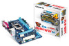
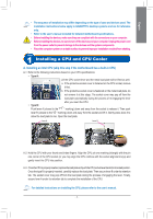
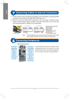
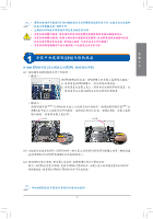
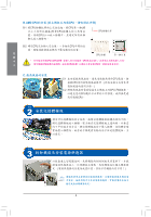
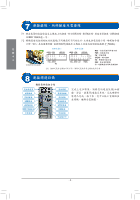
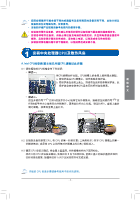
English Step 7 Connecting Cables to Internal Connectors 7-1 Connect cables to internal connectors and headers on the motherboard, including IDE/SATA connectors, and front panel audio, USB, IEEE 1394 headers, etc. 7-2 Attach the front panel module (differs depending on the case design, consisting of power indicator, hard drive activity indicator, speakers, reset switch, power switch, etc.) from the case to the front panel header (F_PANEL) on the motherboard. Front Panel Header Pin Assignments A: +MSG- +PW- +SPEAK- 2 1 +HD- -RES+ NC Pin Assignments B: MSG: Message/Power/Sleep LED +MSG- +PW- +SPEAK- PWR: Power LED PW: Power Switch 20 SPEAK: Speaker 19 HD: Hard Drive Activity LED +HD- -RES+ -CI+ +PWR- RES: Reset Switch CI: Chassis Intrusion Header (Note) The pin assignments for the front panel header may differ by model. Refer to the motherboard user's manual for the actual pin assignments. Step 8 Connecting Peripherals Back Panel of the Case Power Supply PS/2 Keyboard Port DVI-D Port HDMI Port eSATA Port IEEE 1394 Port Audio Jacks Power Switch Power Cord Connector PS/2 Mouse Port D-Sub Port S/PDIF Connector USB Ports RJ-45 LAN Port External Graphics Card Once the steps above have been completed, connect the peripheral devices to the computer, such as the keyboard, mouse, monitor, etc. Then connect the power, turn on the system, and install all required software. - 4 -
-
 1
1 -
 2
2 -
 3
3 -
 4
4 -
 5
5 -
 6
6 -
 7
7 -
 8
8 -
 9
9 -
 10
10 -
11
-
12
-
13
-
14
-
15
-
16
-
17
-
18
-
19
-
20
-
21
-
22
-
23
-
24
-
25
-
26
-
27
-
28
-
29
-
30
-
31
-
32
-
33
-
34
-
35
-
36
-
37
-
38
-
39
-
40
 |
 |