Gigabyte GA-H67MA-D2H Manual - Page 23
CPU_FAN/SYS_FAN Fan Headers, SATA3_0/1 SATA 6Gb/s Connectors, Controlled by H67 Chipset
 |
UPC - 818313012418
View all Gigabyte GA-H67MA-D2H manuals
Add to My Manuals
Save this manual to your list of manuals |
Page 23 highlights
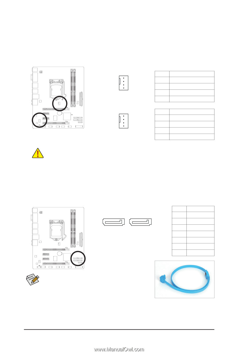
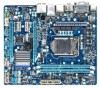
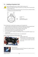
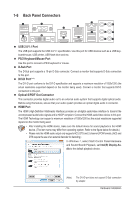
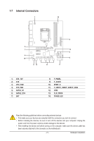
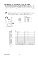
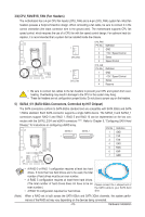
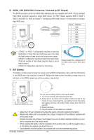
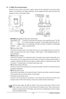
3/4) CPU_FAN/SYS_FAN (Fan Headers) The motherboard has a 4-pin CPU fan header (CPU_FAN) and a 4-pin (SYS_FAN) system fan. Most fan headers possess a foolproof insertion design. When connecting a fan cable, be sure to connect it in the correct orientation (the black connector wire is the ground wire). The motherboard supports CPU fan speed control, which requires the use of a CPU fan with fan speed control design. For optimum heat dissipation, it is recommended that a system fan be installed inside the chassis. 1 CPU_FAN CPU_FAN: Pin No. Definition 1 GND 2 +12V / Speed Control 3 Sense 4 Speed Control 1 SYS_FAN SYS_FAN: Pin No. 1 2 DEBU3G PORT4 Definition GND +12V / Speed Control SenseDEBUG ReserPvOeRT • Be sure to connect fan cables to the fan headers to prevent your CPU and system from overheating. Overheating may result in damage to the CPU or the system may hang. • These fan headers are not configuration jumper blocks. Do not place a jumper cap on the headers. 5) SATA3_0/1 (SATA 6Gb/s Connectors, Controlled by H67 Chipset) The SATA connectors conform to SATA 6Gb/s standard and are compatible with SATA 3Gb/s and SATA 1.5Gb/s standard. Each SATA connector supports a single SATA device. The SATA3_0 and SATA3_1 connectors support RAID 0 and RAID 1. RAID 5 and RAID 10 can be implemented on the two con- nectors with the SATA2_2/3/4 and eSATA connectors . (Note) Refer to Chapter 5, "Configuring SATA Hard Drive(s)," for instructions on configuring a RAID array. SATA3_0 SATA3_1 Pin No. Definition 1 GND 1 7 2 TXP 3 TXN 4 GND 5 RXN 6 RXP 7 GND (Note) • A RAID 0 or RAID 1 configuration requires at least two hard drives. If more than two hard drives are to be used, the total number of hard drives must be an even number. • A RAID 5 configuration requires at least three hard drives. (The total number of hard drives does not have to be an Please connect the L-shaped end of even number.) the SATA cable to your SATA hard • A RAID 10 configuration requires four hard drives. drive. When a RAID set is built across the SATA 6Gb/s and SATA 3Gb/s channels, the system perfor- mance of the RAID set may vary depending on the devices being connected. - 23 - Hardware Installation
-
 1
1 -
2
-
3
-
4
-
5
-
6
-
7
-
8
-
9
-
10
-
11
-
12
-
13
-
14
-
15
-
16
-
17
-
 18
18 -
 19
19 -
 20
20 -
 21
21 -
 22
22 -
 23
23 -
 24
24 -
 25
25 -
 26
26 -
 27
27 -
 28
28 -
29
-
30
-
31
-
32
-
33
-
34
-
35
-
36
-
37
-
38
-
39
-
40
-
41
-
42
-
43
-
44
-
45
-
46
-
47
-
48
-
49
-
50
-
51
-
52
-
53
-
54
-
55
-
56
-
57
-
58
-
59
-
60
-
61
-
62
-
63
-
64
-
65
-
66
-
67
-
68
-
69
-
70
-
71
-
72
-
73
-
74
-
75
-
76
-
77
-
78
-
79
-
80
-
81
-
82
-
83
-
84
-
85
-
86
-
87
-
88
-
89
-
90
-
91
-
92
-
93
-
94
-
95
-
96
-
97
-
98
-
99
-
100
-
101
-
102
-
103
-
104
 |
 |