Gigabyte GA-K8N51GMF User Manual
Gigabyte GA-K8N51GMF Manual
 |
View all Gigabyte GA-K8N51GMF manuals
Add to My Manuals
Save this manual to your list of manuals |
Gigabyte GA-K8N51GMF manual content summary:
- Gigabyte GA-K8N51GMF | User Manual - Page 1
GA-K8N51GMF/ GA-K8N51GMF-RH AMD Socket 754 Processor Motherboard User's Manual Rev. 1004 12ME-N51GMF-1004R * The WEEE marking on the product indicates this product must not be disposed of with user's other household waste and - Gigabyte GA-K8N51GMF | User Manual - Page 2
Motherboard GA-K8N51GMF / GA-K8N51GMF-RH Oct. 26, 2005 Motherboard GA-K8N51GMF GA-K8N51GMF-RH Oct. 26, 2005 - Gigabyte GA-K8N51GMF | User Manual - Page 3
product information and specifications, please carefully read the "Product User Manual". „ For detailed information related to Gigabyte's unique features, please go to "Technology Guide" section on Gigabyte's website to read or download the information you need. For more product details, please - Gigabyte GA-K8N51GMF | User Manual - Page 4
ItemChecklist ...6 OptionalAccessories ...6 GA-K8N51GMF/GA-K8N51GMF-RH Motherboard Layout 7 Block Diagram Memory 14 1-5 Installation of Expansion Cards 15 1-6 I/O Back Panel Introduction 16 1-7 Connectors Introduction 17 Chapter 2 BIOS Setup 27 The Main Menu (For example: BIOS Ver. : F4 - Gigabyte GA-K8N51GMF | User Manual - Page 5
4 Appendix 51 4-1 Unique Software Utilities 51 4-1-1 EasyTune 5 Introduction 52 4-1-2 Xpress Recovery2 Introduction 53 4-1-3 Flash BIOS Method Introduction 55 4-1-4 Configuring SATA Hard Drive(s 64 4-1-5 2- / 4- / 6- / 8- Channel Audio Function Introduction 79 4-2 Troubleshooting 83 - 5 - - Gigabyte GA-K8N51GMF | User Manual - Page 6
Item Checklist IDE Cable x 1 & FDD Cable x 1 Serial ATAII Cable x 1 I/O Shield * The items listed above are for reference only, and are subject to change without notice. Optional Accessories Š 2 Ports USB2.0 Cable (Part Number: 12CR1-1UB030-51/ 51R) Š 2 Ports USB 2.0 + 2 Ports 1394 Cable (Part - Gigabyte GA-K8N51GMF | User Manual - Page 7
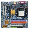
K8N51GMF/GA-K8N51GMF-RH Motherboard Layout MS / KB ATX_12V Socket 754 GA-K8N51GMF GA-K8N51GMF-RH DDR1 DDR2 ATX FDD COMA LPT VGA USB 1394 CI LAN USB IDE1 SATAIIO IDE2 PWR_LED F_PANEL W83627 CD_IN AUDIO1 nVIDIA® GeForce 6100 AUDIO2 CPU_FAN F_AUDIO RTL8201 PCI1 PCIE_16 PCI2 BIOS - Gigabyte GA-K8N51GMF | User Manual - Page 8
) AMD K8 Socket 754 CPU CPUCLK+/-(200MHz) DDR 400/333/266/200MHz DIMM DDR RAM PCI Express x16 Hyper Transport Bus PCI-ECLK x1 (100MHz) 1 PCI Express x1 nVIDIA® GeForce 6100 PCI Bus VT6307 RTL 8201 RJ45 nVIDIA® nForce 410 ATA33/66/100/133 IDE Channels 2 Serial ATAII BIOS Floppy LPC BUS - Gigabyte GA-K8N51GMF | User Manual - Page 9
instructions below: 1. Please turn off the computer and unplug its power cord. 2. When handling the motherboard uncertain about any installation steps or have a problem related to the use of the product, violating the conditions recommended in the user manual. 3. Damage due to improper installation. - Gigabyte GA-K8N51GMF | User Manual - Page 10
Š 1 front panel connector Š 1 front audio connector Š 1 CD In connector Š 2 USB 2.0/1.1 connectors for additional 4 USB 2.0/1.1 ports by cables Š 1 IEEE1394 connector for additional 1 port by cable Š 1 SPDIF In/Out connector Š 1 power LED connector GA-K8N51GMF(-RH) Motherboard - 10 - - Gigabyte GA-K8N51GMF | User Manual - Page 11
1 RJ-45 port Š 6 audio jacks (Line In / Line Out BIOS Additional Features Š Supports @BIOS Š Supports Download Center Š Supports Q-Flash Š Supports EasyTune (only supports Hardware Monitor function)(Note 2) Š Supports Xpress Install Š Supports Xpress Recovery2 Š Supports is supported will - Gigabyte GA-K8N51GMF | User Manual - Page 12
make sure that the motherboard supports the CPU. 2. memory, hard drive, etc. 1-3-1 Installation of the CPU Check the processor pins to see that none are bent. Move the socket lever to the unlocked position as shown in Figure 1.(90o to the plane of the motherboard GA-K8N51GMF(-RH) Motherboard - 12 - - Gigabyte GA-K8N51GMF | User Manual - Page 13
CPU. Install all the heat sink components (Please refer to the heat sink manual for detailed installation instructions). Fig.2 Please connect the heat sink power connector to the CPU_FAN connector located on the motherboard so that the heat sink can properly function to prevent CPU overheating. The - Gigabyte GA-K8N51GMF | User Manual - Page 14
in one direction. Insert the DIMM memory module vertically into the DIMM socket. Then push it down. Fig.2 Close the plastic clip at both edges of the DIMM sockets to lock the DIMM module. Reverse the installation steps when you wish to remove the DIMM module. GA-K8N51GMF(-RH) Motherboard - 14 - - Gigabyte GA-K8N51GMF | User Manual - Page 15
Read the related expansion card's instruction document before install the expansion Press the expansion card firmly into expansion slot in motherboard. 4. Be sure the metal contacts on the card if necessary, setup BIOS utility of expansion card from BIOS. 8. Install related driver from the operating - Gigabyte GA-K8N51GMF | User Manual - Page 16
supports USB controller. If your OS does not support USB controller, please contact OS vendor for possible patch or driver upgrade. For more information please contact your OS or device(s) vendors. LAN connector. MIC In Microphone can be connected to MIC In jack. GA-K8N51GMF(-RH) Motherboard - 16 - - Gigabyte GA-K8N51GMF | User Manual - Page 17
to this connector. Side Speaker Out Connect the side surround speakers to this connector. You can use audio software to configure 2-/4-/6-/8-channel audio functioning. 1-7 Connectors Introduction 1 2 5 13 10 3 9 6 7 8 17 15 14 4 16 11 12 1) ATX_12V 2) ATX (Power Connector) 3) CPU_FAN - Gigabyte GA-K8N51GMF | User Manual - Page 18
before plugging in the power cord ; Otherwise, please do not remove it. 42 31 Pin No. 1 2 3 4 Definition GND GND +12V +12V GA-K8N51GMF(-RH) Motherboard Pin No. Definition 13 1 1 3.3V 2 3.3V 3 GND 4 +5V 5 GND 6 +5V 7 GND 8 Power Good 9 5V SB(stand by +5V) 10 +12V 11 - Gigabyte GA-K8N51GMF | User Manual - Page 19
connector is used to connect the FDD cable while the other end of the cable connects to the FDD drive. The types of FDD drives supported are: 360KB, 720KB, 1.2MB, 1.44MB and 2.88MB. Please connect the red power connector wire to the pin1 position. 34 33 2 1 - 19 - Hardware Installation - Gigabyte GA-K8N51GMF | User Manual - Page 20
(for information on settings, please refer to the instructions located on the IDE device). 40 39 2 IDE2 BIOS setting for the Serial ATA and install the proper driver in order to work properly. 1 7 7 1 Pin No. 1 2 3 4 5 6 7 Definition GND TXP TXN GND RXN RXP GND GA-K8N51GMF(-RH) Motherboard - Gigabyte GA-K8N51GMF | User Manual - Page 21
. To find out if the chassis you are buying support front audio connector, please contact your dealer. Please note, you can have the alternative of using front audio connector or of using rear audio connector to play sound. Pin No. Definition 1 MIC 10 9 2 GND 3 MIC_BIAS 2 1 4 POWER - Gigabyte GA-K8N51GMF | User Manual - Page 22
English 10) CD_IN (CD In Connector) Connect CD-ROM or DVD-ROM audio out to the connector. 1 Pin No. Definition 1 CD-L 2 GND 3 GND 4 CD-R 11) F_ USB1 2 Power (5V) 3 USB DX- 1 9 4 USB Dy- 5 USB DX+ 6 USB Dy+ 7 GND 8 GND 9 No Pin 10 NC GA-K8N51GMF(-RH) Motherboard - 22 - - Gigabyte GA-K8N51GMF | User Manual - Page 23
Intrusion, Case Open) This 2-pin connector allows your system to detect if the chassis cover is removed. You can check the "Case Opened" status in BIOS Setup. Pin No. Definition 1 1 Signal 2 GND - 23 - Hardware Installation - Gigabyte GA-K8N51GMF | User Manual - Page 24
1 Short: Clear CMOS 15) BATTERY GA-K8N51GMF(-RH) Motherboard Danger of explosion if battery is incorrectly replaced. Replace only with the same or equivalent type recommended by the manufacturer. Dispose of used batteries according to the manufacturer's instructions. If you want to erase CMOS - Gigabyte GA-K8N51GMF | User Manual - Page 25
5 TPB+ 6 TPB- 7 Power(12V) 8 Power(12V) 9 No Pin 10 GND 17) SPDIF_IO (SPDIF In/Out) The SPDIF output is capable of providing digital audio to external speakers or compressed AC3 data to an external Dolby Digital Decoder. Use this feature only when your stereo system has digital input - Gigabyte GA-K8N51GMF | User Manual - Page 26
English GA-K8N51GMF(-RH) Motherboard - 26 - - Gigabyte GA-K8N51GMF | User Manual - Page 27
update or backup BIOS without entering the operating system. @BIOS is a Windows-based utility that does not require users to boot to DOS before upgrading BIOS but directly download and update BIOS from CMOS, only for Option Page Setup Menu Load the Optimized Defaults Q-Flash utility - Gigabyte GA-K8N51GMF | User Manual - Page 28
CDROM USB-HDD Legacy LAN KL:Move Enter :Accept ESC:Exit The Main Menu (For example: BIOS Ver. : F4) Once you enter Award BIOS CMOS Setup Utility, BIOS when somehow the system works not stable as usual. This action makes the system reset to the default for stability. GA-K8N51GMF(-RH) Motherboard - Gigabyte GA-K8N51GMF | User Manual - Page 29
English „ Standard CMOS Features This setup page includes all the items in standard compatible BIOS. „ Advanced BIOS Features This setup page includes all the items of Award special enhanced features. „ Integrated Peripherals This setup page includes all onboard peripherals. „ Power Management - Gigabyte GA-K8N51GMF | User Manual - Page 30
Support Halt On Base Memory Extended Memory Total Memory ESC: Exit F7: Optimized Defaults F1 BIOS Manual User can manually input the correct settings Access Mode Use this to set the access mode for the hard drive. The four options are: CHS/LBA/Large/Auto(default:Auto) GA-K8N51GMF(-RH) Motherboard - Gigabyte GA-K8N51GMF | User Manual - Page 31
capacity 1.44M, 3.5" 3.5 inch double-sided drive; 1.44M byte capacity. (Default value) 2.88M, 3.5" 3.5 inch double-sided drive; 2.88M byte capacity. Floppy 3 Mode Support detected and you will be prompted. All Errors Whenever the BIOS detects a non-fatal error the system will be stopped. - Gigabyte GA-K8N51GMF | User Manual - Page 32
more memory installed on the motherboard. Extended Memory The BIOS determines how much extended memory is present during the POST. This is the amount of memory located above 1 MB in the CPU's memory address map. Total Memory This item displays the memory size that used. GA-K8N51GMF(-RH) Motherboard - Gigabyte GA-K8N51GMF | User Manual - Page 33
Select +/-/PU/PD: Value F5: Previous Values F10: Save ESC: Exit F7: Optimized Defaults F1: General Help Hard Disk Boot Priority Select boot sequence for Legacy LAN Select your boot device priority by Legacy LAN. Disabled Disable this function. Boot Up Floppy Seek During POST, BIOS will - Gigabyte GA-K8N51GMF | User Manual - Page 34
monitor display from which card when you install a PCI card and a PCI Express VGA card on the motherboard. PCI Slot Set Init Display First to PCI VGA card. Onboard VGA Set Init Display First to onboard there is a graphics card on the PCI Express slot or not. GA-K8N51GMF(-RH) Motherboard - 34 - - Gigabyte GA-K8N51GMF | User Manual - Page 35
On-Chip USB USB Keyboard Support USB Mouse Support Onboard Audio Function Onboard LAN Function Onboard LAN Boot ROM Onboard 1394 Function +/-/PU/PD: Value F10: Save F6: Fail-Safe Defaults ESC: Exit F1: General Help F7: Optimized Defaults SATA-II RAID function (Default value) - 35 - BIOS Setup - Gigabyte GA-K8N51GMF | User Manual - Page 36
onboard LAN chip function.(Default value) Disabled Disable onboard LAN chip function. Onboard LAN Boot ROM This function decide whether to invoke the boot ROM of the onboard LAN chip. Enabled Disabled Enable this function. Disable this function. (Default value) GA-K8N51GMF(-RH) Motherboard - Gigabyte GA-K8N51GMF | User Manual - Page 37
. 2E8/IRQ3 Enable onboard Serial port 1 and address is 2E8/IRQ3. Disabled Disable onboard Serial port 1. Onboard Serial Port 2 Auto 3F8/IRQ4 BIOS will automatically setup the port 2 address. Enable onboard Serial port 2 and address is 3F8/IRQ4. 2F8/IRQ3 3E8/IRQ4 Enable onboard Serial port - Gigabyte GA-K8N51GMF | User Manual - Page 38
Level` KLJI: Move Enter: Select +/-/PU/PD: Value F5: Previous Values F10: Save ESC: Exit F7: Optimized Defaults F1: General Help ACPI Suspend Type S1(POS) Set ACPI suspend type to S1/POS(Power 1~31 Time (hh: mm: ss) Alarm : (0~23) : (0~59) : (0~59) GA-K8N51GMF(-RH) Motherboard - 38 - - Gigabyte GA-K8N51GMF | User Manual - Page 39
, the system will be in "Off" state. (Default value) Full-On When AC-power back to the system, the system always in "On" state. - 39 - BIOS Setup - Gigabyte GA-K8N51GMF | User Manual - Page 40
Menu Level` KLJI: Move Enter: Select +/-/PU/PD: Value F5: Previous Values F10: Save ESC: Exit F7: Optimized Defaults F1: General Help PCI 1 IRQ Assignment Auto 3,4,5,7,9,10,11,12,14,15 PCI 2 IRQ Default value) Set IRQ 3,4,5,7,9,10,11,12,14,15 to PCI 2. GA-K8N51GMF(-RH) Motherboard - 40 - - Gigabyte GA-K8N51GMF | User Manual - Page 41
Select +/-/PU/PD: Value F5: Previous Values F10: Save ESC: Exit F7: Optimized Defaults F1: General Help Reset Case Open Status Disabled Don't reset . (Note) Whether the CPU Smart FAN Control function is supported will depend on the CPU you install. For more detailed information please - Gigabyte GA-K8N51GMF | User Manual - Page 42
+/-/PU/PD: Value F5: Previous Values F10: Save ESC: Exit F7: Optimized Defaults F1: General Help Incorrect using these features may cause the increase of the DIMM voltage, damage to the memory may occur. Normal Set DIMM OverVoltage Control to Normal ! GA-K8N51GMF(-RH) Motherboard - 42 - - Gigabyte GA-K8N51GMF | User Manual - Page 43
Setup Utility-Copyright (C) 1984-2005 Award Software ` Standard CMOS Features ` Advanced BIOS Features ` Integrated Peripherals ` Power Management Setup ` PnP/PCI Configurations ` PC this field loads the factory defaults for BIOS and Chipset Features which the system automatically detects. - 43 - Gigabyte GA-K8N51GMF | User Manual - Page 44
Advance BIOS Features Menu, you will be prompted for the password every time the system is rebooted or any time you try to enter Setup Menu. If you select "Setup" at "Password Check" in Advance BIOS Features Menu, you will be prompted only when you try to enter Setup. GA-K8N51GMF(-RH) Motherboard - Gigabyte GA-K8N51GMF | User Manual - Page 45
to Setup Utility. 2-12 Exit Without Saving CMOS Setup Utility-Copyright (C) 1984-2005 Award Software ` Standard CMOS Features ` Advanced BIOS Features ` Integrated Peripherals ` Power Management Setup ` PnP/PCI Configurations ` PC Health Status ` Frequency/Voltage Control Esc: Quit F8: Q-Flash - Gigabyte GA-K8N51GMF | User Manual - Page 46
English GA-K8N51GMF(-RH) Motherboard - 46 - - Gigabyte GA-K8N51GMF | User Manual - Page 47
in Windows XP. Insert the driver CD-title that came with your motherboard into your CD-ROM drive, the driver CD-title will auto start and show the installation guide. If not, please double click the CD-ROM device icon in "My computer", and execute the Setup.exe. 3-1 Install Chipset Drivers After - Gigabyte GA-K8N51GMF | User Manual - Page 48
Application This page displays all the tools that Gigabyte developed and some free software, you can choose anyone you want and press "install" to install them. 3-3 Software Information This page lists the contents of software and drivers in this CD-title. GA-K8N51GMF(-RH) Motherboard - 48 - - Gigabyte GA-K8N51GMF | User Manual - Page 49
English 3-4 Hardware Information This page lists all device you have for this motherboard. 3-5 Contact Us Please see the last page for details. - 49 - Drivers Installation - Gigabyte GA-K8N51GMF | User Manual - Page 50
English GA-K8N51GMF(-RH) Motherboard - 50 - - Gigabyte GA-K8N51GMF | User Manual - Page 51
short-circuit the "Clear CMOS" pins or the battery on the motherboard to reset the system back to factory default settings. Instead, S.O.S. users. Download Center Download Center allows users to quickly download and update their BIOS as well as the latest drivers for their system. Download Center - Gigabyte GA-K8N51GMF | User Manual - Page 52
for special enhancement for CPU and Memory, 3) Smart-Fan control for managing fan speed control of both CPU cooling fan and North-Bridge Chipset cooling fan, 4) PC health for 5 software (Note) EasyTune 5 functions may vary depending on different motherboards. GA-K8N51GMF(-RH) Motherboard - 52 - - Gigabyte GA-K8N51GMF | User Manual - Page 53
quick backup and restoration of hard disk data. Supporting Microsoft operating systems including Windows XP/2000/NT/98/Me and DOS, and file CD/DVD: Award Modular BIOS v6.00PG, An Energy Star Ally Copyright (C) 1984-2005, Award Software, Inc. GA-K8N51GMF-9-RH F3a . . . . :BIOS Setup/Q-Flash, - Gigabyte GA-K8N51GMF | User Manual - Page 54
As this is a BIOS-related issue, it can be solved by BIOS update) GA-K8U GA-K8NXP-9 GA-K8U-9 GA-K8N Ultra-9 GA-K8NXP-SLI GA-K8NF-9 (PCB Ver. 1.0) GA-K8N Ultra-SLI GA-K8NE (PCB Ver. 1.0) GA-K8N Pro-SLI GA-K8NMF-9 GA-K8N51GMF(-RH) Motherboard - 54 - GA-8N-SLI Royal GA-8N-SLI Pro GA-8N-SLI - Gigabyte GA-K8N51GMF | User Manual - Page 55
from end-users. Before You Begin: Before you start updating BIOS with the Q-FlashTM utility, please follow the steps below first. 1. Download the latest BIOS for your motherboard from Gigabyte's website. 2. Extract the BIOS file downloaded and save the BIOS file (the one with model name.Fxx. For - Gigabyte GA-K8N51GMF | User Manual - Page 56
Enter key on your keyboard to enable execution of the task. Action bar: Contains the names of four actions needed to operate the Q-Flash/Dual BIOS utility. Pressing the buttons mentioned on your keyboards to perform these actions. GA-K8N51GMF(-RH) Motherboard - 56 - - Gigabyte GA-K8N51GMF | User Manual - Page 57
flash and press Enter. In this example, we only download one BIOS file to the floppy disk so only one BIOS file, 8KNXPU.Fba, is listed. Please confirm again you have the correct BIOS file for your motherboard. Dual BIOS Utility Boot From Main Bios Main ROM Type/Size SST 49LF003A Backup ROM Type - Gigabyte GA-K8N51GMF | User Manual - Page 58
Primary Master : FUJITSU MPE3170AT ED-03-08 Primary Slave : None Secondary Master : CREATIVEDVD-RM DVD1242E BC101 Secondary Slave : None Press DEL to enter SETUP / Dual BIOS / Q-Flash / F9 For Xpress Recovery 09/23/2003-i875P-6A79BG03C-00 GA-K8N51GMF(-RH) Motherboard - 58 - - Gigabyte GA-K8N51GMF | User Manual - Page 59
Disk Type... Press Y on your keyboard to save and exit. Part Two: Updating BIOS with Q-FlashTM Utility on Single-BIOS Motherboards. This part guides users of single-BIOS motherboards how to update BIOS using the Q-FlashTM utility. CMOS Setup Utility-Copyright (C) 1984-2004 Award Software Standard - Gigabyte GA-K8N51GMF | User Manual - Page 60
SyCs:tRemeset F10:Power Off Do not turn off power or reset your system at this stage!! After BIOS file is read, you'll see a confirmation dialog box asking you "Are you sure to update BIOS?" Please do not take out the floppy disk when it begins flashing BIOS. GA-K8N51GMF(-RH) Motherboard - 60 - - Gigabyte GA-K8N51GMF | User Manual - Page 61
file becomes F4 after updating Award Modular BIOS v6.00PG, An Energy Star Ally Copyright (C) 1984-2003, Award Software, Inc. Intel 845GE AGPSet BIOS for 8GE800 F4 Check System Health OK Main Processor : Intel Pentium(R) 4 1.7GHz (100x17.0) Memory Testing : 122880K - Gigabyte GA-K8N51GMF | User Manual - Page 62
b. Click "Update New BIOS" c. Please select "All Files" in dialog box while opening the old file. d. Please search for BIOS unzip file, downloading from internet or any other methods (such as: N51GMF.F1). e. Complete update process following the instruction. GA-K8N51GMF(-RH) Motherboard - 62 - - Gigabyte GA-K8N51GMF | User Manual - Page 63
II, be sure that motherboard's model name in BIOS unzip file are the same as your motherboard's. Otherwise, your system won't boot. III. In method I, if the BIOS file you need cannot be found in @BIOSTM server, please go onto Gigabyte's web site for downloading and updating it according to method - Gigabyte GA-K8N51GMF | User Manual - Page 64
model and capacity). If you do not want to create RAID, you may prepare only one hard drive. (b) An empty formatted floppy disk. (c) Windows XP/2000 setup disk. (d) Driver CD for your motherboard. (1) do not want to create RAID array on the SATA controller. GA-K8N51GMF(-RH) Motherboard - 64 - - Gigabyte GA-K8N51GMF | User Manual - Page 65
Keyboard Support USB Mouse Support Onboard Audio Function Onboard LAN Function Onboard LAN Boot F6: Fail-Safe Defaults Figure 2 ESC: Exit F1: General Help F7: Optimized Defaults The BIOS Setup menus described in this section may not show the exact settings for your motherboard. The actual BIOS - Gigabyte GA-K8N51GMF | User Manual - Page 66
under the Advanced BIOS Features menu. In the Hard Disk Boot Priority submenu, select the model of the SATA hard drive onto which you wish to install Microsoft Windows 2000/XP. You should menu. : Move PU/PD/+/-: Change Priority F10: Save Figure 4 GA-K8N51GMF(-RH) Motherboard - 66 - ESC: Exit - Gigabyte GA-K8N51GMF | User Manual - Page 67
Windows installation CD-ROM, set First Boot Device under the Advanced BIOS Features menu to CDROM (Figure 5). CMOS Setup Utility-Copyright (C) 1984-2006 Award Software Advanced BIOS Save and exit BIOS Setup. +/-/PU/PD: Value F10: Save F6: Fail-Safe Defaults Figure 5 ESC: Exit F1: General Help - Gigabyte GA-K8N51GMF | User Manual - Page 68
- Striping Block: Optimal Free Disks Loc Disk Model 2.0.M ST3120026AS 2.1.M ST3120026AS Capacity 111.79GB 111.79GB Array Disks Loc Disk Model [ ] Add Capacity [ ] Del [ESC] Quit [F6] Back [F7] Finish [TAB] Navigate [ ] Select [ENTER] Popup Figure 7 GA-K8N51GMF(-RH) Motherboard - 68 - - Gigabyte GA-K8N51GMF | User Manual - Page 69
a New Array - RAID Mode: Striping Striping Block: Optimal Free Disks Loc Disk Model Capacity Array Disks Loc Disk Model [ ] Add 2.0.M ST3120026AS 2.1.M ST3120026AS Capacity 111.79GB 111.79GB [ ] Del [ESC] Quit [F6] Back [F7] Finish [TAB] Navigate [ ] Select [ENTER] Popup Figure 8 Step - Gigabyte GA-K8N51GMF | User Manual - Page 70
the Free Disks Capacity Clear disk daAtarr?ay Disks Loc Disk Model [Y[C] Yle]EaArSdddisk[Nd]a11tNa..01O?..MM ST3120026AS ST3120026AS [Y] YES [N] NO [ ] Del Capacity 111.79GB 111.79GB [ESC] Quit [F6] Back [F7] Finish [TAB] Navigate [ ] Select [ENTER] Popup Figure 9 GA-K8N51GMF(-RH) Motherboard - Gigabyte GA-K8N51GMF | User Manual - Page 71
where you should see detailed information about RAID mode, disk block size, disk model name, and disk capacity, etc. Array 2 : NVIDIA STRIPE 223.57G - Array Detail - RAID Mode: Striping Striping Width : , you can proceed to install the SATA controller driver and operating system. - 71 - Appendix - Gigabyte GA-K8N51GMF | User Manual - Page 72
a startup disk: Use an alternative system and insert the GIGABYTE motherboard driver CD-ROM. From the CD-ROM drive folder, double click the MENU.exe file in the BootDrv folder (Figure 14). A command prompt window will open similar to that in Figure 13. GA-K8N51GMF(-RH) Motherboard Figure 14 - 72 - - Gigabyte GA-K8N51GMF | User Manual - Page 73
prepared the SATA driver disk and configured BIOS settings, you are ready to install Windows 2000/XP onto your SATA hard drive with the SATA driver. The following is an example of Windows XP installation. Step 1: Restart your system to boot from the Windows 2000/XP Setup disk and press F6 as soon as - Gigabyte GA-K8N51GMF | User Manual - Page 74
disk or copy the correct SATA driver again from the motherboard driver CD. "*" If you want to create RAID, select both NVIDIA RAID CLASS DRIVER and then NVIDIA nForce Storage Controller. If you do not create RAID, select NVIDIA nForce Storage Controller only. GA-K8N51GMF(-RH) Motherboard - 74 - - Gigabyte GA-K8N51GMF | User Manual - Page 75
19 After the SATA controller driver installation is completed, you can proceed with the Windows 2000/XP installation. WindowsXP Professional Setup Welcome to Setup. This port of the Setup program prepares Microsoft(R) Windows (R) XP to run on your computer. To set up Windows XP now, press ENTER. To - Gigabyte GA-K8N51GMF | User Manual - Page 76
instructions: Step 1: Install Windows 2000 onto a selected hard drive. Download and install Windows 2000 Service Pack 4 from Microsoft's website. Step 2: After system restarts, press Del to enter system BIOS F6: Fail-Safe Defaults GA-K8N51GMF(-RH) Motherboard Figure 22 - 76 - ESC: - Gigabyte GA-K8N51GMF | User Manual - Page 77
Then press CTRL+X to exit the NVIDIA RAID BIOS. Restart the computer to boot into Windows 2000. RAID Mode: Striping MediaShield RAID Utility July 27 2005 - Define a New Array - Striping Block: Optimal Free Disks Loc Disk Model Capacity Clear disk daAtarr?ay Disks Loc Disk Model [Y[] Y]EASdd - Gigabyte GA-K8N51GMF | User Manual - Page 78
instructions. Select the desired Free Disk(s) downloads/servicepacks/sp4/HFdeploy.htm Note: If users choose not to install Windows 2000 Service Pack 3 or 4, RAID is still supported on Windows 2000. However, users will not be able to create a bootable RAID volume. GA-K8N51GMF(-RH) Motherboard - Gigabyte GA-K8N51GMF | User Manual - Page 79
Windows XP) Stereo Speakers Connection and Settings: We recommend that you use the speaker with amplifier to acquire the best sound effect if the stereo output is applied. STEP 1: Connect the stereo speakers or earphone to "Line Out". Line Out STEP 2 : Following installation of the audio driver - Gigabyte GA-K8N51GMF | User Manual - Page 80
of the audio driver, you find a Sound Effect icon on the lower right hand taskbar. Click the icon to select the function. STEP 3: Click "Speaker Configuration" then click on the left selection bar and select "4CH Speaker" to complete 4 channel audio configuration. GA-K8N51GMF(-RH) Motherboard - 80 - Gigabyte GA-K8N51GMF | User Manual - Page 81
channels to "Rear Speaker Out", and the Center/Subwoofer channels to "Center/Subwoofer Speaker Out". STEP 2 : Following installation of the audio driver, you find a Sound Effect icon on the lower right hand taskbar. Click the icon to select the function. STEP 3: Click "Speaker Configuration" then - Gigabyte GA-K8N51GMF | User Manual - Page 82
of the audio driver, you find a Sound Effect icon on audio configuration. Sound Effect Configuration: At the sound effect menu, users can adjust sound option settings as desired. Front Speaker Out Center/Subwoofer Speaker Out Rear Speaker Out Side Speaker Out GA-K8N51GMF(-RH) Motherboard - Gigabyte GA-K8N51GMF | User Manual - Page 83
Troubleshooting Below is a collection of general asked questions. To check general asked questions based on a specific motherboard model, please log on to GIGABYTE's website. Question 1: I cannot see some options that were included in previous BIOS after updating BIOS steps in the manual. If your - Gigabyte GA-K8N51GMF | User Manual - Page 84
English GA-K8N51GMF(-RH) Motherboard - 84 - - Gigabyte GA-K8N51GMF | User Manual - Page 85
- 85 - Appendix English - Gigabyte GA-K8N51GMF | User Manual - Page 86
English GA-K8N51GMF(-RH) Motherboard - 86 - - Gigabyte GA-K8N51GMF | User Manual - Page 87
.us y Mexico G.B.T Inc (USA) Tel: +1-626-854-9338 x 215 (Soporte de habla hispano) FAX: +1-626-854-9339 Correo: [email protected] Tech. Support: http://rma.gigabyte-usa.com Web address: http://www.gigabyte-latam.com y Japan NIPPON GIGA-BYTE CORPORATION WEB address : http://www.gigabyte.co.jp - Gigabyte GA-K8N51GMF | User Manual - Page 88
Ltd. in SERBIA & MONTENEGRO WEB address : http://www.gigabyte.co.yu y GIGABYTE Global Service System To submit a technical or non-technical (Sales/ Marketing) question, please link to : http://ggts.gigabyte.com.tw Then select your language to enter the system. GA-K8N51GMF(-RH) Motherboard - 88 -
-
 1
1 -
 2
2 -
 3
3 -
 4
4 -
 5
5 -
 6
6 -
 7
7 -
8
-
9
-
10
-
11
-
12
-
13
-
14
-
15
-
16
-
17
-
18
-
19
-
20
-
21
-
22
-
23
-
24
-
25
-
26
-
27
-
28
-
29
-
30
-
31
-
32
-
33
-
34
-
35
-
36
-
37
-
38
-
39
-
40
-
41
-
42
-
43
-
44
-
45
-
46
-
47
-
48
-
49
-
50
-
51
-
52
-
53
-
54
-
55
-
56
-
57
-
58
-
59
-
60
-
61
-
62
-
63
-
64
-
65
-
66
-
67
-
68
-
69
-
70
-
71
-
72
-
73
-
74
-
75
-
76
-
77
-
78
-
79
-
80
-
81
-
82
-
83
-
84
-
85
-
86
-
87
-
88
 |
 |

GA-K8N51GMF/
GA-K8N51GMF-RH
AMD Socket 754 Processor Motherboard
User's Manual
Rev. 1004
12ME-N51GMF-1004R
*
The WEEE marking on the product indicates this product must not be disposed of with user's other household waste
and must be handed over to a designated collection point for the recycling of waste electrical and electronic equipment!!
*
The WEEE marking applies only in European Union's member states.