Gigabyte GA-K8U User Manual
Gigabyte GA-K8U Manual
 |
View all Gigabyte GA-K8U manuals
Add to My Manuals
Save this manual to your list of manuals |
Gigabyte GA-K8U manual content summary:
- Gigabyte GA-K8U | User Manual - Page 1
GA-K8U AMD Socket 754 Processor Motherboard User's Manual Rev. 1002 12ME-K8U-1002 - Gigabyte GA-K8U | User Manual - Page 2
Motherboard GA-K8U Jan. 26, 2005 Motherboard GA-K8U Jan. 26, 2005 - Gigabyte GA-K8U | User Manual - Page 3
product information and specifications, please carefully read the "Product User Manual". „ For detailed information related to Gigabyte's unique features, please go to the "Technology Guide" section on Gigabyte's website to read or download the information you need. For more product details, please - Gigabyte GA-K8U | User Manual - Page 4
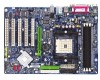
GA-K8U Motherboard Layout 6 Block Diagram ...7 Chapter 1 Hardware Installation 9 1-1 Considerations Prior to Installation 9 1-2 Feature Summary 10 1-3 Installation of the CPU and Heatsink 11 1-3-1 Installation of the CPU 11 1-3-2 Installation of the Heatsink 12 1-4 Installation of Memory - Gigabyte GA-K8U | User Manual - Page 5
49 4-1 Unique Software Utilities 49 4-1-1 EasyTune 5 Introduction 49 4-1-2 Xpress Recovery Introduction 50 4-1-3 Flash BIOS Method Introduction 53 4-1-4 Serial ATA BIOS Setting Utility Introduction 62 4-1-5 2- / 4- / 6- / 8- Channel Audio Function Introduction 70 4-2 Troubleshooting 78 - 5 - - Gigabyte GA-K8U | User Manual - Page 6
GA-K8U Motherboard Layout MS/KB COMA COMB R_USB ATX_12V Socket 754 DDR3 DDR2 DDR1 ATX FDD LPT LAN USB AUDIO F_AUDIO CD_IN RTL 8100C AGP CODEC SUR_CEN SMSC LPC47M997-NR SPDIF_IO GAME IR CPU_FAN CLR_CMOS BAT PWR_FAN GA-K8U IDE1 IDE2 PCI1 SYS_FAN PCI2 ULi M1689 PCI3 SATA2 PCI4 BIOS - Gigabyte GA-K8U | User Manual - Page 7
RJ45 LAN AMD K8 Socket 754 CPU CPUCLK+/-(800MHz) DDR 400(Note)/333/266/200MHz DIMM DDR RAM Hyper Transport Bus ULi M1689 BIOS 2 Serial ATA ATA33/66 want to install DDR400 memory modules in your system, please install either one double-sided or two single-sided DDR400 memory modules. The DDR400 - Gigabyte GA-K8U | User Manual - Page 8
- 8 - - Gigabyte GA-K8U | User Manual - Page 9
instructions below: 1. Please turn off the computer and unplug its power cord. 2. When handling the motherboard motherboard. Installation Notices 1. Prior to installation, please do not remove the stickers on the motherboard the motherboard or or have a problem related to the the user manual. 3. Damage - Gigabyte GA-K8U | User Manual - Page 10
English 1-2 Feature Summary CPU Š Socket 754 for AMD AthlonTM 64 processor (K8) Š 1600MH/z system bus Š Supports core frequencies in excess of 3000+ and faster Chipset Š ULi M1689 Chipset Memory Š 3 DDR DIMM memory slots (supports up to 3GB memory) Š Supports DDR 400 (Note 1)/333/266/200 - Gigabyte GA-K8U | User Manual - Page 11
: 1. Please make sure that the motherboard supports the CPU. 2. Please take note memory, hard drive, etc. 1-3-1 Installation of the CPU Check the processor pins to see that none are bent. Move the socket lever to the unlocked position as shown in Figure 1.(90o to the plane of the motherboard - Gigabyte GA-K8U | User Manual - Page 12
(Please refer to the heat sink manual for detailed installation instructions). Fig.2 Please connect the heat sink power connector to the CPU_FAN connector located on the motherboard so that the heat sink can dissipation or using extreme care when removing the heat sink. GA-K8U Motherboard - 12 - - Gigabyte GA-K8U | User Manual - Page 13
in only one direction. If you are unable to insert the module, please switch the direction. The motherboard supports DDR memory modules, whereby BIOS will automatically detect memory capacity and specifications. Memory modules are designed so that they can be inserted only in one direction. The - Gigabyte GA-K8U | User Manual - Page 14
outlined below: 1. Read the related expansion card's instruction document before install the expansion card into the computer. on the computer, if necessary, setup BIOS utility of expansion card from BIOS. 8. Install related driver from the operating system. Installing a GA-K8U Motherboard - 14 - - Gigabyte GA-K8U | User Manual - Page 15
OS supports USB controller. If your OS does not support USB controller, please contact OS vendor for possible patch or driver upgrade. For more information please contact your OS MIC In jack. You can use audio software to configure 2-/4-/6-/8-channel audio functioning. - 15 - Hardware Installation - Gigabyte GA-K8U | User Manual - Page 16
9) PWR_LED 10) BAT 2 6 7 10 4 5 8 9 16 11 11) F_PANEL 12) F_AUDIO 13) CD_IN 14) SUR_CEN 15) SPDIF_IO 16) F_USB1 / F_USB2 17) IR 18) GAME 19) CLR_CMOS GA-K8U Motherboard - 16 - - Gigabyte GA-K8U | User Manual - Page 17
(Power Connector) With the use of the power connector, the power supply can supply enough stable power to all the components on the motherboard. Before connecting the power connector, please make sure that all components and devices are properly installed. Align the power connector with its proper - Gigabyte GA-K8U | User Manual - Page 18
a foolproof connection design. Most coolers are designed with color-coded power connector wires. A red power connector wire indicates a drives supported are: 360KB, 720KB, 1.2MB, 1.44MB and 2.88MB. Please connect the red power connector wire to the pin1 position. 34 33 GA-K8U Motherboard 2 1 - - Gigabyte GA-K8U | User Manual - Page 19
the other as Slave (for information on settings, please refer to the instructions located on the IDE device). 40 39 2 IDE1 1 IDE2 8) up to 150MB/s transfer rate. Please refer to the BIOS setting for the Serial ATA and install the proper driver in order to work properly. Pin No. Definition 1 - Gigabyte GA-K8U | User Manual - Page 20
1 MPD+ 1 2 MPD- 3 MPD- 10) BAT (Battery) GA-K8U Motherboard Danger of explosion if battery is incorrectly replaced. Replace only with the same or equivalent type recommended by the manufacturer. Dispose of used batteries according to the manufacturer's instructions. If you want to erase CMOS - Gigabyte GA-K8U | User Manual - Page 21
English 11) F_PANEL (Front Panel Jumper) Please connect the power LED, PC speaker, reset switch and power switch etc of your chassis front panel to the F_PANEL connector according to the pin assignment below. Message LED/ Power/ Sleep LED Speaker Connector Power Switch MSG+ MSG- PW+ PWSPEAK+ - Gigabyte GA-K8U | User Manual - Page 22
9 10 4 Power 5 Front Audio (R) 6 Rear Audio (R)/ Return R 7 NC 8 No Pin 9 Front Audio (L) 10 Rear Audio (L)/ Return L 13) CD_IN (CD In Connector) Connect CD-ROM or DVD-ROM audio out to the connector. Pin No. Definition 1 1 CD-L 2 GND 3 GND 4 CD-R GA-K8U Motherboard - 22 - - Gigabyte GA-K8U | User Manual - Page 23
OUTL SUR OUTR GND No Pin CENTER_OUT BASS_OUT AUX_L AUX_R 15) SPDIF_IO (SPDIF In / Out Connector) The SPDIF output is capable of providing digital audio to external speakers or compressed AC3 data to an external Dolby Digital Decoder. Use this feature only when your stereo system has digital input - Gigabyte GA-K8U | User Manual - Page 24
while you connect the IR. Please contact your nearest dealer for optional IR device. Pin No. Definition 1 Power 1 2 No Pin 3 IR RX 4 GND 5 IR TX GA-K8U Motherboard - 24 - - Gigabyte GA-K8U | User Manual - Page 25
GAME (Game Connector) This connector supports joystick, MIDI keyboard and other relate audio devices. Check the pin assignment while force feedback joystick, go to Midi Port Address under the Integrated Peripherals menu in BIOS Setup to specify the base I/O address. 19) CLR_CMOS (Clear CMOS) You - Gigabyte GA-K8U | User Manual - Page 26
English GA-K8U Motherboard - 26 - - Gigabyte GA-K8U | User Manual - Page 27
BIOS, either GIGABYTE's Q-Flash or @BIOS utility can be used. Q-Flash allows the user to quickly and easily update or backup BIOS without entering the operating system. @BIOS is a Windows-based utility that does not require users to boot to DOS before upgrading BIOS but directly download and update - Gigabyte GA-K8U | User Manual - Page 28
. „ Standard CMOS Features This setup page includes all the items in standard compatible BIOS. „ Advanced BIOS Features This setup page includes all the items of Award special enhanced features. „ of the system parameters which the system would be in safe configuration. GA-K8U Motherboard - 28 - - Gigabyte GA-K8U | User Manual - Page 29
system. „ Save & Exit Setup Save CMOS value settings to CMOS and exit setup. „ Exit Without Saving Abandon all CMOS value changes and exit setup. - 29 - BIOS Setup - Gigabyte GA-K8U | User Manual - Page 30
during POST(default) • None Select this if no SATA IDE devices are used and the system will skip the automatic detection step and allow for faster system start up. Access Mode Use this to set the access mode for the hard drive. The two options are: Large/Auto(default:Auto) GA-K8U Motherboard - Gigabyte GA-K8U | User Manual - Page 31
byte capacity. Floppy 3 Mode Support (for Japan Area) Disabled memory installed on the motherboard, or 640K for systems with 640K or more memory installed on the motherboard. Extended Memory The BIOS determines how much extended memory is present during the POST. This is the amount of memory - Gigabyte GA-K8U | User Manual - Page 32
Features CMOS Setup Utility-Copyright (C) 1984-2004 Award Software Advanced BIOS Features ` Hard Disk Boot Priority First Boot Device Second Boot Device Third Boot Device Password Check [Press access to Setup page if the correct password is not entered at the prompt. GA-K8U Motherboard - 32 - - Gigabyte GA-K8U | User Manual - Page 33
-Copyright (C) 1984-2004 Award Software Integrated Peripherals OnChip Audio OnChip SATA OnChip SATA Mode On-Chip Primary IDE On-Chip Secondary IDE IDE DMA transfer access Onboard H/W LAN USB 1.1 Controller USB Keyboard Support USB Mouse Support USB 2.0 Controller OnBoard LAN Boot ROM Onboard Serial - Gigabyte GA-K8U | User Manual - Page 34
Support Enabled Enable USB keyboard support. Disabled Disable USB keyboard support. (Default value) USB Mouse Support Enabled Disabled Enable USB mouse support. Disable USB mouse support function. Onboard Serial Port 1 Auto BIOS will automatically setup the port 1 GA-K8U Motherboard - 34 - - Gigabyte GA-K8U | User Manual - Page 35
. (Default value) 5 Set Midi Port IRQ to 5. (Note) If you want to use a force feedback joystick, set Midi Port Address to 330 or 300. - 35 - BIOS Setup - Gigabyte GA-K8U | User Manual - Page 36
When AC-power back to the system, the system will be in "Off" state. (Default value) Full-On Memory When AC-power back to the system, the system always in "On" state. When AC-power back to the . (Default value) Enabled Enable USB device can wakeup system from S3. GA-K8U Motherboard - 36 - - Gigabyte GA-K8U | User Manual - Page 37
left button to power on the system. Mouse/Any KEY Press any key or double click on mouse left button to power on the system. GA-K8U Motherboard - 37 - - Gigabyte GA-K8U | User Manual - Page 38
) Set IRQ 3,4,5,7,9,10,11,12,14,15 to PCI 4. Auto assign IRQ to PCI 5. (Default value) Set IRQ 3,4,5,7,9,10,11,12,14,15 to PCI 5. GA-K8U Motherboard - 38 - - Gigabyte GA-K8U | User Manual - Page 39
's voltage status automatically. Current CPU/SYSTEM FAN Speed (RPM) Detect CPU/SYSTEM fan speed status automatically. ESC: Exit F1: General Help F7: Optimized Defaults - 39 - BIOS Setup - Gigabyte GA-K8U | User Manual - Page 40
) +5%, +7.5%, +10% Increase voltage range as user selected. AGP OverVoltage Control Auto Supply voltage as AGP required. (Default value) +5%, +7.5%, +10% Increase voltage range as user selected. GA-K8U Motherboard - 40 - - Gigabyte GA-K8U | User Manual - Page 41
Utility-Copyright (C) 1984-2004 Award Software ` Standard CMOS Features ` Advanced BIOS Features ` Integrated Peripherals ` Power Management Setup ` PnP/PCI Configurations ` Selecting this field loads the factory defaults for BIOS and Chipset Features which the system automatically detects. - 41 - Gigabyte GA-K8U | User Manual - Page 42
" in Advance BIOS Features Menu, you will be prompted for the password every time the system is rebooted or any time you try to enter Setup Menu. If you select "Setup" at "Password Check" in Advance BIOS Features Menu, you will be prompted only when you try to enter Setup. GA-K8U Motherboard - 42 - Gigabyte GA-K8U | User Manual - Page 43
to Setup Utility. 2-12 Exit Without Saving CMOS Setup Utility-Copyright (C) 1984-2004 Award Software ` Standard CMOS Features ` Advanced BIOS Features ` Integrated Peripherals ` Power Management Setup ` PnP/PCI Configurations ` PC Health Status ` Frequency/Voltage Control ESC: Quit F8: Q-Flash - Gigabyte GA-K8U | User Manual - Page 44
English GA-K8U Motherboard - 44 - - Gigabyte GA-K8U | User Manual - Page 45
in Windows XP. Insert the driver CD-title that came with your motherboard into your CD-ROM drive, the driver CD-title will auto start and show the installation guide. If not, please double click the CD-ROM device icon in "My computer", and execute the Setup.exe. 3-1 Install Chipset Drivers After - Gigabyte GA-K8U | User Manual - Page 46
3-2 Software Application This page displays all the tools that Gigabyte developed and some free software, you can choose anyone you want and press "install" to install them. 3-3 Software Information This page lists the contents of software and drivers in this CD-title. GA-K8U Motherboard - 46 - - Gigabyte GA-K8U | User Manual - Page 47
English 3-4 Hardware Information This page lists all device you have for this motherboard. 3-5 Contact Us Please see the last page for details. - 47 - Drivers Installation - Gigabyte GA-K8U | User Manual - Page 48
English GA-K8U Motherboard - 48 - - Gigabyte GA-K8U | User Manual - Page 49
5 presents the most convenient Windows based system performance enhancement and Memory, 3) Smart-Fan control for managing fan speed control of both CPU cooling fan and North-Bridge Chipset Shows the current functions status Log on to GIGABYTE website Display EasyTuneTM 5 Help file Quit or - Gigabyte GA-K8U | User Manual - Page 50
power on. . . Verifying DMI Pool Data Boot from CD: Boot from CD: Xpress Recovery V1.0 (C) Copy Right 2003. GIGABYTE Technology CO. , Ltd. 1. Execute Backup Utility 2. Execute Restore Utility 3. Remove Backup Image 4. Set Password 5. Exit and Restart Build 2011 GA-K8U Motherboard - 50 - - Gigabyte GA-K8U | User Manual - Page 51
BIOS for 8IPE1000MT F1 Check System Health OK . . . Press DEL to enter SETUP / Q-Flash, F9 For Xpress Recovery 08/16/2002-I845GE-6A69YG01C-00 F9 For Xpress Recovery Xpress Recovery V1.0 (C) Copy Right 2003. GIGABYTE OS and all required driver and software installations are complete. - 51 - - Gigabyte GA-K8U | User Manual - Page 52
scan your system and back up data as a backup image in your hard drive. Not all systems support access to Xpress Recovery by pressing the F9 key during computer power on. If this is the case remove password requirement. 5. Exit and Restart: Exit and restart your computer. GA-K8U Motherboard - 52 - - Gigabyte GA-K8U | User Manual - Page 53
Part One. If your motherboard has single-BIOS, please refer to Part Two. Part One: Updating BIOS with Q-FlashTM Utility on Dual BIOS Motherboards. Some of Gigabyte motherboards are equipped with dual BIOS. In the BIOS menu of the motherboards supporting Q-Flash and Dual BIOS, the Q-Flash utility and - Gigabyte GA-K8U | User Manual - Page 54
Enter key on your keyboard to enable execution of the task. Action bar: Contains the names of four actions needed to operate the Q-Flash/Dual BIOS utility. Pressing the buttons mentioned on your keyboards to perform these actions. GA-K8U Motherboard - 54 - - Gigabyte GA-K8U | User Manual - Page 55
flash and press Enter. In this example, we only download one BIOS file to the floppy disk so only one BIOS file, 8KNXPU.Fba, is listed. Please confirm again you have the correct BIOS file for your motherboard. Dual BIOS Utility Boot From Main Bios Main ROM Type/Size SST 49LF004A Backup ROM Type - Gigabyte GA-K8U | User Manual - Page 56
Primary Master : FUJITSU MPE3170AT ED-03-08 Primary Slave : None Secondary Master : CREATIVEDVD-RM DVD1242E BC101 Secondary Slave : None Press DEL to enter SETUP / Dual BIOS / Q-Flash / F9 For Xpress Recovery 09/23/2003-i875P-6A79BG03C-00 GA-K8U Motherboard - 56 - - Gigabyte GA-K8U | User Manual - Page 57
Disk Type... Press Y on your keyboard to save and exit. Part Two: Updating BIOS with Q-FlashTM Utility on Single-BIOS Motherboards. This part guides users of single-BIOS motherboards how to update BIOS using the Q-FlashTM utility. CMOS Setup Utility-Copyright (C) 1984-2004 Award Software Standard - Gigabyte GA-K8U | User Manual - Page 58
ReseEt SyCs:tRemeset F10:Power Off Do not trun off power or reset your system at this stage!! After BIOS file is read, you'll see a confirmation dialog box asking you "Are you sure to update BIOS?" Please do not take out the floppy disk when it begins flashing BIOS. GA-K8U Motherboard - 58 - - Gigabyte GA-K8U | User Manual - Page 59
file becomes F4 after updating Award Modular BIOS v6.00PG, An Energy Star Ally Copyright (C) 1984-2003, Award Software, Inc. Intel 845GE AGPSet BIOS for 8GE800 F4 Check System Health OK Main Processor : Intel Pentium(R) 4 1.7GHz (100x17.0) Memory Testing : 122880K OK - Gigabyte GA-K8U | User Manual - Page 60
"Internet Update" icon. b. Click "Update New BIOS". c. Please select "All Files" in dialog box while opening the old file. d. Please search for BIOS unzip file, downloading from internet or any other methods (such as: K8U.D3). e. Complete update process following the instruction. GA-K8U Motherboard - Gigabyte GA-K8U | User Manual - Page 61
II, be sure that motherboard's model name in BIOS unzip file are the same as your motherboard's. Otherwise, your system won't boot. III. In method I, if the BIOS file you need cannot be found in @BIOSTM server, please go onto Gigabyte's website for downloading and updating it according to method II - Gigabyte GA-K8U | User Manual - Page 62
English 4-1-4 Serial ATA BIOS Setting Utility Introduction RAID Levels levels, security levels and implementation costs. The RAID levels which the ULi M1689 chipset supports are RAID 0, RAID 1,and JBOD. RAID 0 (Striping) a RAID and does not support fault tolerance. GA-K8U Motherboard - 62 - - Gigabyte GA-K8U | User Manual - Page 63
, SCSI, or SATA. 3) Enter the motherboard BIOS and locate RAID setup (Please refer to the section on Integrated Peripherals). 4) Enter RAID setup in the BIOS and select the RAID type (For instance, enter Ctrl + A to select ULi RAID; Ctrl + S to select Silicon Image). 5) Complete driver installation - Gigabyte GA-K8U | User Manual - Page 64
Array A : RAID Array B : RAID Array C : Capacity Mode SATA 1 SATA 1 RAID Type Capacity 120034 MB 120034 MB Stripe Size RAID Array/Type for RAID 0. (as Figure below) RAID BIOS Setup Utility (c) 2004 ULi Corporation www.uli.com.tw Create RAID 0 Striping for GA-K8U Motherboard - 64 - - Gigabyte GA-K8U | User Manual - Page 65
SATA 1 Capacity 120034 MB 120034 MB RAID Array/Type RAID Array A : RAID Array B : RAID Array C : Capacity RAID Type Stripe Size RAID Name After the RAID array has been created successfully, its information shows up at RAID Array List. RAID BIOS Setup Utility (c) 2004 ULi Corporation - Gigabyte GA-K8U | User Manual - Page 66
data is inconsistent in two drives. RAID BIOS Setup Utility (c) 2004 ULi Corporation www.uli.com.tw Create RAID 0 Striping for SATA 1 SATA 1 Capacity 120034 MB 120034 MB RAID Array/Type RAID Array A : RAID Array B : RAID Array C : Capacity RAID Type Stripe Size RAID Name GA-K8U Motherboard - Gigabyte GA-K8U | User Manual - Page 67
four and the minimum is two. RAID BIOS Setup Utility (c) 2004 ULi Corporation www.uli.com.tw Create RAID 0 Striping for Performance Model J Channel 1 Master : ST3120026AS J Channel 2 Master : ST3120026AS Mode SATA 1 SATA 1 Capacity 120034 MB 120034 MB RAID Array/Type RAID Array A : RAID - Gigabyte GA-K8U | User Manual - Page 68
and then the data in drives is destroyed. RAID Array List automatically updates itself. 6. Rebuild RAID Array When a drive is replaced or BIOS detects a broken RAID, the user can use Rebuild RAID Array to . The process status bar shows up during the duplication process. GA-K8U Motherboard - 68 - - Gigabyte GA-K8U | User Manual - Page 69
on your motherboard during OS installation. Without the driver, the hard disk may not be recognized during the Windows setup process. First of all, you have to copy the driver for the SATA controller on your motherboard from the motherboard driver CD to a floppy disk. See the instructions below - Gigabyte GA-K8U | User Manual - Page 70
of the audio driver, you'll will find a Sound Effect icon on the lower right hand taskbar. Click the icon to select the function. STEP 3: Click "Speaker Configuration" then click on the left selection bar and select "2CH Speaker" to complete 2 channel audio configuration. GA-K8U Motherboard - 70 - Gigabyte GA-K8U | User Manual - Page 71
Setup STEP 1: Connect the Front Speakers to "Line Out", the Rear Speakers to "Line In". STEP 2: Following installation of the audio driver, you'll find a Sound Effect icon on the lower right hand taskbar. Click the icon to select the function. Line In (Rear Speaker Out) Line - Gigabyte GA-K8U | User Manual - Page 72
"Line In", and the Center/Subwoofer Speakers to "MIC In". STEP 2: Following installation of the audio driver, you'll find a Sound Effect icon on the lower right hand taskbar. Click the icon to bar and select "6CH Speaker" to complete 6 channel audio configuration. GA-K8U Motherboard - 72 - - Gigabyte GA-K8U | User Manual - Page 73
. STEP 2: Connect the Surround-Kit to the SUR_CEN connector located on the motherboard. STEP 3: There are two methods of 8 channel audio configuration: Method 1: Connect the front channels to the "Line Out" port located on the audio panel and the rear channels to the Surround-Kit "REAR R/L" port - Gigabyte GA-K8U | User Manual - Page 74
(This method requires UAJ function) STEP 4: Following installation of the audio driver, you'll find a Sound Effect icon on the lower right hand channel audio configuration. Sound Effect Configuration: At the sound effect menu, users can adjust sound option settings as desired. GA-K8U Motherboard - - Gigabyte GA-K8U | User Manual - Page 75
(Optional Device) A "SPDIF output" connector is available on the motherboard. Cable with rear bracket could link to the "SPDIF output" connector and fix it with screw. 2. Connect SPDIF device to the motherboard. 3. Connect SPDIF to the SPDIF decoder. (Note) If you want to use both of the 8 channel - Gigabyte GA-K8U | User Manual - Page 76
to Line Out jack, and microphone to MIC In jack. Auto-detecting: Please connect the devices to the right jacks as above. A window will appear as right picture if you setup the devices properly. Please note that 3D audio function will only appear when 3D audio inputs. GA-K8U Motherboard - 76 - - Gigabyte GA-K8U | User Manual - Page 77
: If the device picture shows different from what you set, please press "Manual Selection" to set. UAJ Introduction UAJ (Universal Audio Jack) has a very smart feature: It will switch signal automatically when user plugs his audio device to the wrong jack (Line-in/ Line-out). That means users - Gigabyte GA-K8U | User Manual - Page 78
English 4-2 Troubleshooting Below is a collection of general asked questions. To check general asked questions based on a specific motherboard model, please log on to http://www.gigabyte.com.tw Question 1: I cannot see some options that were included in previous BIOS after updating BIOS. Why? - Gigabyte GA-K8U | User Manual - Page 79
to case. AMI BIOS Beep Codes *Computer gives 1 short beep when system boots successfully. *Except for beep code 8, these codes are always fatal. 1 beep: Refresh failure 2 beeps: Parity error 3 beeps: Base 64K memory failure 4 beeps: Timer not operational 5 beeps: Processor error 6 beeps: 8042 - gate - Gigabyte GA-K8U | User Manual - Page 80
English GA-K8U Motherboard - 80 - - Gigabyte GA-K8U | User Manual - Page 81
- 81 - Appendix English - Gigabyte GA-K8U | User Manual - Page 82
English GA-K8U Motherboard - 82 - - Gigabyte GA-K8U | User Manual - Page 83
- 83 - Appendix English - Gigabyte GA-K8U | User Manual - Page 84
English GA-K8U Motherboard - 84 - - Gigabyte GA-K8U | User Manual - Page 85
- 85 - Appendix English - Gigabyte GA-K8U | User Manual - Page 86
English GA-K8U Motherboard - 86 - - Gigabyte GA-K8U | User Manual - Page 87
Milton Keynes, MK1 1DR, UK, England TEL: +44-1908-362700 FAX: +44-1908-362709 Tech. Support : http://uk.giga-byte.com/TechSupport/ServiceCenter.htm Non-Tech. Support(Sales/Marketing) : http://ggts.gigabyte.com.tw/nontech.asp WEB address : http://uk.giga-byte.com The Netherlands GIGA-BYTE TECHNOLOGY - Gigabyte GA-K8U | User Manual - Page 88
://www.gigabyte.ru Poland Representative Office Of Giga-Byte Technology Co., Ltd. POLAND Tech. Support : http://tw.giga-byte.com/TechSupport/ServiceCenter.htm Non-Tech. Support(Sales/Marketing) : http://ggts.gigabyte.com.tw/nontech.asp WEB address : http://www.gigabyte.pl GA-K8U Motherboard - 88
-
 1
1 -
 2
2 -
 3
3 -
 4
4 -
 5
5 -
 6
6 -
 7
7 -
8
-
9
-
10
-
11
-
12
-
13
-
14
-
15
-
16
-
17
-
18
-
19
-
20
-
21
-
22
-
23
-
24
-
25
-
26
-
27
-
28
-
29
-
30
-
31
-
32
-
33
-
34
-
35
-
36
-
37
-
38
-
39
-
40
-
41
-
42
-
43
-
44
-
45
-
46
-
47
-
48
-
49
-
50
-
51
-
52
-
53
-
54
-
55
-
56
-
57
-
58
-
59
-
60
-
61
-
62
-
63
-
64
-
65
-
66
-
67
-
68
-
69
-
70
-
71
-
72
-
73
-
74
-
75
-
76
-
77
-
78
-
79
-
80
-
81
-
82
-
83
-
84
-
85
-
86
-
87
-
88
 |
 |

GA-K8U
AMD Socket 754 Processor Motherboard
User's Manual
Rev. 100
2
12ME-K8U-100
2