Gigabyte GA-K8VT800 User Manual
Gigabyte GA-K8VT800 Manual
 |
View all Gigabyte GA-K8VT800 manuals
Add to My Manuals
Save this manual to your list of manuals |
Gigabyte GA-K8VT800 manual content summary:
- Gigabyte GA-K8VT800 | User Manual - Page 1
GA-K8VT800-RH AMD Socket 754 Processor Motherboard User's Manual Rev. 2001 12ME-K8VT800R-2001R * The WEEE marking on the product indicates this product must not be disposed of with user's other household waste and must be handed over to a designated collection point for the recycling of waste - Gigabyte GA-K8VT800 | User Manual - Page 2
Motherboard GA-K8VT800-RH JUNE. 21, 2006 Motherboard GA-K8VT800-RH June. 21, 2006 - Gigabyte GA-K8VT800 | User Manual - Page 3
product. „ For detailed product information and specifications, please carefully read the "Product User Manual". „ For detailed information related to Gigabyte's unique features, please go to the "Technology Guide" section on Gigabyte's website to read or download the information you need. For more - Gigabyte GA-K8VT800 | User Manual - Page 4
Table of Contents ItemChecklist ...6 OptionalAccessories ...6 GA-K8VT800-RH Motherboard Layout 7 Block Diagram ...8 Chapter 1 Hardware Installation 9 1-1 Considerations Prior to Installation 9 1-2 Feature Summary 10 1-3 Installation of the CPU and Heatsink 12 1-3-1 Installation of the CPU 12 - Gigabyte GA-K8VT800 | User Manual - Page 5
Us ...49 Chapter 4 Appendix 51 4-1 Unique Software Utilities 51 4-1-1 Xpress Recovery Introduction 51 4-1-2 Flash BIOS Method Introduction 54 4-1-3 Serial ATA BIOS Setting Utility Introduction 63 4-1-4 2- / 4- / 6- / 8- Channel Audio Function Introduction 69 4-2 Troubleshooting 77 - 5 - - Gigabyte GA-K8VT800 | User Manual - Page 6
Power Cable x 1 2 Ports USB2.0 Cable x 1 SATA Cable x 2 I/O Shield * The items listed above are for reference only, and are subject to change without notice. Optional Accessories Š 2 Ports USB2.0 Cable (Part Number: 12CR1-1UB030-51/R) Š 8-Channel Audio Combo Kit (Part Number: 12CR1-1SPAUD-21 - Gigabyte GA-K8VT800 | User Manual - Page 7
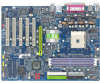
GA-K8VT800-RH DDR1 DDR2 DDR3 GA-K8VT800-RH Motherboard Layout KB_MS CPU_FAN ATX_12V Socket 754 ATX COMA COMB LPT USB USB LAN AUDIO F_AUDIO RTL 8100C CODEC VIA K8T800 AGP PCI1 CD_IN PCI2 FDD BATTERY IDE1 IDE2 IT8705F BIOS SPDIF_IO IR SUR_CEN PCI3 SATA1 SATA0 PCI4 VIA - Gigabyte GA-K8VT800 | User Manual - Page 8
/266/200 DIMM DDR RAM VIA K8T800 AGPCLK66MHz 33 MHz 48 MHz 14.318 MHz VIA VT8237R / VT8237R+ PS/2 KB/Mouse IT8705F Floppy LPT Port BIOS PCICLK (33MHz) AC97 2 SATA 8 USB ATA66/100/133 24 MHz CODEC Ports Ports IDE Channels 33 MHz COM Ports MIC LINE-IN LINE-OUT - 8 - - Gigabyte GA-K8VT800 | User Manual - Page 9
of violating the conditions recommended in the user manual. 3. Damage due to improper installation. 4. Damage due to use of uncertified components. 5. Damage due to use exceeding the permitted parameters. 6. Product determined to be an unofficial Gigabyte product. - 9 - Hardware Installation - Gigabyte GA-K8VT800 | User Manual - Page 10
Š CPU temperature detection Š CPU / System fan speed detection Š CPU / System fan failure warning (Note 1) It is recommended to use SATA (1.5Gb/s) hard disks. (Note 2) To set up an 8 channel audio configuration, you must use Audio Combo Kit (optional device). GA-K8VT800-RH Motherboard - 10 - - Gigabyte GA-K8VT800 | User Manual - Page 11
0) or mirroring (RAID 1) function supports JBOD function supports data transfer rate of up to 150 MB/s supports a maximum of 2 SATA connections Use of licensed AWARD BIOS Supports Q-Flash Supports @BIOS Supports EasyTune Over Voltage via BIOS (CPU/ DDR/ AGP) Over Clock via BIOS (CPU) ATX form factor - Gigabyte GA-K8VT800 | User Manual - Page 12
. Move the socket lever to the locked position while holding pressure on the center of the processor. Please be careful when installing the CPU. The CPU will not fit if positioned incorrectly. Rather than applying force, please change the positioning of the CPU. GA-K8VT800-RH Motherboard - 12 - - Gigabyte GA-K8VT800 | User Manual - Page 13
manual for detailed installation instructions). Fig.2 Please connect the heat sink power connector to the CPU_FAN connector located on the motherboard direction. The motherboard supports DDR memory modules, whereby BIOS will automatically detect memory capacity and specifications. Memory modules - Gigabyte GA-K8VT800 | User Manual - Page 14
DIMM Socket DDR2 -SS --DS -SS SS -DS DS -SS DS DDR3 --SS --DS -SS SS -DS DS SS DS Max. Memory Speed DDR 400 DDR 400 DDR 400 DDR 400 DDR 400 DDR 400 DDR 400 DDR 400 DDR 400 DDR 400 DDR 333 DDR 400 DDR 400 DDR 333 GA-K8VT800-RH Motherboard - Gigabyte GA-K8VT800 | User Manual - Page 15
Read the related expansion card's instruction document before install the expansion 3. Press the expansion card firmly into expansion slot in motherboard. 4. Be sure the metal contacts on the card necessary, setup BIOS utility of expansion card from BIOS. 8. Install related driver from the operating - Gigabyte GA-K8VT800 | User Manual - Page 16
Connect the stereo speakers, earphone or front surround speakers to this connector. MIC In Microphone can be connected to MIC In jack. You can use audio software to configure 2-/4-/6-/8-channel audio function. GA-K8VT800-RH Motherboard - 16 - - Gigabyte GA-K8VT800 | User Manual - Page 17
English 1-7 Connectors Introduction 1 3 10 11 12 13 15 1) ATX_12V 2) ATX (Power Connector) 3) CPU_FAN 4) SYS_FAN 5) FDD 6) IDE1 / IDE2 7) SATA0 / SATA1 8) PWR_LED 9) F_PANEL 2 5 17 6 7 4 16 14 89 10) F_AUDIO 11) CD_IN 12) SPDIF_IO 13) SUR_CEN 14) F_USB1 / F_USB2 15) IR 16) CLR_CMOS 17) - Gigabyte GA-K8VT800 | User Manual - Page 18
power connector, the power supply can supply enough stable power to all the components on the motherboard. Before connecting the power connector, please make sure that all components and devices are properly GND 16 GND 17 GND 18 -5V 19 +5V 20 +5V GA-K8VT800-RH Motherboard - 18 - - Gigabyte GA-K8VT800 | User Manual - Page 19
English 3/4) CPU_FAN / SYS_FAN (Cooler Fan Power Connector) The cooler fan power connector supplies a +12V power voltage via a 3-pin power connector and possesses a foolproof connection design. Most coolers are designed with color-coded power connector wires. A red power connector wire indicates a - Gigabyte GA-K8VT800 | User Manual - Page 20
end of the cable connects to the FDD drive. The types of FDD drives supported are: 360KB, 720KB, 1.2MB, 1.44MB instructions located on the IDE device). Before attaching the IDE cable, please take note of the foolproof groove in the IDE connector. 39 1 IDE1 IDE2 40 2 GA-K8VT800-RH Motherboard - Gigabyte GA-K8VT800 | User Manual - Page 21
SATA0/ SATA1 (Serial ATA Connector) Serial ATA can provide up to 150MB/s transfer rate. Please refer to the BIOS setting for the Serial ATA and install the proper driver in order to work properly. Pin No. Definition 1 GND 1 7 2 TXP 3 TXN 4 GND 5 RXN 6 RXP 7 GND 8) PWR_LED PWR_LED - Gigabyte GA-K8VT800 | User Manual - Page 22
1: Power Pin 2- Pin 3: NC Pin 4: Data(-) Open: Normal Close: Reset Hardware System Open: Normal Close: Power On/Off Pin 1: LED anode(+) Pin 2: LED cathode(-) NC GA-K8VT800-RH Motherboard - 22 - - Gigabyte GA-K8VT800 | User Manual - Page 23
. To find out if the chassis you are buying support front audio connector, please contact your dealer. Please note, you can have the alternative of using front audio connector or of using rear audio connector to play sound. Pin No. Definition 10 9 1 MIC 2 GND 3 MIC_BIAS 2 1 4 POWER - Gigabyte GA-K8VT800 | User Manual - Page 24
(SPDIF In / Out Connector) The SPDIF output is capable of providing digital audio to external speakers or compressed AC3 data to an external Dolby Digital Decoder. 7 Pin No. 1 2 3 4 5 6 7 8 Definition SUR OUTL SUR OUTR GND No Pin CENTER_OUT BASS_OUT AUX_L AUX_R GA-K8VT800-RH Motherboard - 24 - - Gigabyte GA-K8VT800 | User Manual - Page 25
will make the device unable to work or even damage it. For optional front USB cable, please contact your local dealer. Pin No. Definition 1 Power 2 10 2 Power 1 9 3 USB DX- 4 USB Dy- 5 USB DX+ 6 USB Dy+ 7 GND 8 GND 9 No Pin 10 NC 15) IR Check the pin assignments carefully - Gigabyte GA-K8VT800 | User Manual - Page 26
1 Short: Clear CMOS 1 17) BATTERY GA-K8VT800-RH Motherboard Danger of explosion if battery is incorrectly replaced. Replace only with the same or equivalent type recommended by the manufacturer. Dispose of used batteries according to the manufacturer's instructions. If you want to erase CMOS - Gigabyte GA-K8VT800 | User Manual - Page 27
- 27 - Hardware Installation English - Gigabyte GA-K8VT800 | User Manual - Page 28
English GA-K8VT800-RH Motherboard - 28 - - Gigabyte GA-K8VT800 | User Manual - Page 29
BIOS, either GIGABYTE's Q-Flash or @BIOS utility can be used. Q-Flash allows the user to quickly and easily update or backup BIOS without entering the operating system. @BIOS is a Windows-based utility that does not require users to boot to DOS before upgrading BIOS but directly download and update - Gigabyte GA-K8VT800 | User Manual - Page 30
exact settings for your motherboard. The Main Menu (For example: BIOS Ver. : E8) Once you enter Award BIOS CMOS Setup Utility, Fail-Safe Defaults Load Optimized Defaults Set Supervisor Password Set User Password Save & Exit Setup Exit Without Saving KLJI: Select GA-K8VT800-RH Motherboard - 30 - - Gigabyte GA-K8VT800 | User Manual - Page 31
. „ Set Supervisor Password Change, set, or disable password. It allows you to limit access to the system and Setup, or just to Setup. „ Set User Password Change, set, or disable password. It allows you to limit access to the system. „ Save & Exit Setup Save CMOS value settings to CMOS and - Gigabyte GA-K8VT800 | User Manual - Page 32
will skip the automatic detection step and allow for faster system start up. Access Mode Use this to set the access mode for the hard drive. The two options are: Large/Auto(default:Auto) GA-K8VT800-RH Motherboard - 32 - - Gigabyte GA-K8VT800 | User Manual - Page 33
88M, 3.5" 3.5 inch double-sided drive; 2.88M byte capacity. Floppy 3 Mode Support (for Japan Area) Disabled Normal Floppy Drive. (Default value) Drive A Drive A is 3 mode Floppy Drive. Drive B Drive B is 3 mode Floppy Drive. Both Drive A & B are 3 mode Floppy Drives. Halt on The category - Gigabyte GA-K8VT800 | User Manual - Page 34
2004 Award Software Advanced BIOS Features ` Hard USB-FDD Select your boot device priority by USB-FDD. USB-ZIP Select your boot device priority by USB-ZIP. USB-CDROM Select your boot device priority by USB-CDROM. USB-HDD Select your boot device priority by USB GA-K8VT800-RH Motherboard - 34 - - Gigabyte GA-K8VT800 | User Manual - Page 35
Peripherals IDE DMA transfer access OnChip IDE Channel 0 OnChip IDE Channel 1 OnChip Serial ATA SATA Mode AC97 Audio USB 1.1 Controller USB 2.0 Controller USB Keyboard Support USB Mouse Support Onboard H/W LAN OnBoard LAN Boot ROM Onboard FDC Controller Onboard Serial Port 1 Onboard Serial - Gigabyte GA-K8VT800 | User Manual - Page 36
USB 2.0 controller. (Default value) USB Keyboard Support Enabled Enable USB keyboard support. Disabled Disable USB keyboard support. (Default value) USB Mouse Support Enabled Disabled Enable USB mouse support. Disable USB mouse support 3F8/IRQ4 BIOS will GA-K8VT800-RH Motherboard - 36 - - Gigabyte GA-K8VT800 | User Manual - Page 37
to 330. Disable this function. (Default value) Midi Port IRQ 5 Set Midi Port IRQ to 5. 10 Set Midi Port IRQ to 10. (Default value) - 37 - BIOS Setup - Gigabyte GA-K8VT800 | User Manual - Page 38
Set ACPI suspend type to S3/STR(Suspend To RAM). USB Device Wake-Up From S3 Disabled Enabled Disable USB Device Wake-Up from S3. (Default value) Enable USB Device Wake-Up from S3. Soft-Off by PWRBTN click on PS/2 mouse left button to power on the system. GA-K8VT800-RH Motherboard - 38 - - Gigabyte GA-K8VT800 | User Manual - Page 39
to POWER ON system. If Resume by Alarm is Enabled. Date (of Month) Alarm : Everyday, 1~31 Time (hh: mm: ss) Alarm: (0~23) : (0~59) : (0~59) - 39 - BIOS Setup - Gigabyte GA-K8VT800 | User Manual - Page 40
[Auto] [Auto] [Auto] [Auto] Item Help Menu Level` Device(s) using this INT: USB 1.1 Host Cntrlr -Bus 0 Dev16 Func 1 USB 1.1 Host Cntrlr -Bus 0 Dev16 Func 0 KLJI: Move Enter: Select F5: Previous Values (Default value) Set IRQ 3,4,5,7,9,10,11,12,14,15 to PCI 4. GA-K8VT800-RH Motherboard - 40 - - Gigabyte GA-K8VT800 | User Manual - Page 41
speed status automatically. CPU/SYSTEM FAN Fail Warning Disabled Disable fan fail warning function disable. (Default value) Enabled Enable fan fail warning function enable. - 41 - BIOS Setup - Gigabyte GA-K8VT800 | User Manual - Page 42
Defaults F1: General Help Incorrect using these features may cause your system broken. For power end-user use only. K8 CPU Clock Ratio Default Set CPU clock ratio to default. (Default value) x4 Increase AGP voltage +0.1V. +0.2v Increase AGP voltage +0.2V. GA-K8VT800-RH Motherboard - 42 - - Gigabyte GA-K8VT800 | User Manual - Page 43
Top Performance ` Advanced BIOS Features Load Fail-Safe Configurations PC Health Status Disabled Enabled Set User Password Save & Exit Setup ` Frequency/ Windows XP, but works smoothly with Windows NT. Therefore, if your system is not perform enough, the reliability or stability problem - Gigabyte GA-K8VT800 | User Manual - Page 44
BIOS Features Menu, you will be prompted for the password every time the system is rebooted or any time you try to enter Setup Menu. If you select "Setup" at "Password Check" in Advance BIOS Features Menu, you will be prompted only when you try to enter Setup. GA-K8VT800-RH Motherboard - 44 - Gigabyte GA-K8VT800 | User Manual - Page 45
Setup Save & Exit Setup Type "Y" will quit the Setup Utility and save the user setup value to RTC CMOS. Type "N" will return to Setup Utility. 2-13 Exit (C) 1984-2004 Award Software ` Standard CMOS Features ` Advanced BIOS Features ` Integrated Peripherals ` Power Management Setup ` PnP/PCI - Gigabyte GA-K8VT800 | User Manual - Page 46
English GA-K8VT800-RH Motherboard - 46 - - Gigabyte GA-K8VT800 | User Manual - Page 47
Installation Pictures below are shown in Windows XP. Insert the driver CD-title that came with your motherboard into your CD-ROM drive, the driver CD-title will auto start and show the installation guide. If not, please double click the CD-ROM device icon in "My computer", and execute the Setup - Gigabyte GA-K8VT800 | User Manual - Page 48
Software Application This page displays all the tools that Gigabyte developed and some free software, you can choose anyone you want and press "install" to install them. 3-3 Software Information This page lists the contents of software and drivers in this CD-title. GA-K8VT800-RH Motherboard - 48 - - Gigabyte GA-K8VT800 | User Manual - Page 49
English 3-4 Hardware Information This page lists all device you have for this motherboard. 3-5 Contact Us Please see the last page for details. - 49 - Drivers Installation - Gigabyte GA-K8VT800 | User Manual - Page 50
English GA-K8VT800-RH Motherboard - 50 - - Gigabyte GA-K8VT800 | User Manual - Page 51
drive is not working properly, the user can restore the drive to its original state. 1. Supports BIOS menu, select "Advanced BIOS Feature" and set to boot from CD-ROM. Insert the provided driver CD into your CD drive, then save and exit the BIOS Recovery V1.0 (C) Copy Right 2003. GIGABYTE Technology - Gigabyte GA-K8VT800 | User Manual - Page 52
future by pressing the F9 key. 2. System storage capacity as well as drive reading/writing speed will affect backup speed. 3. It is recommended that Xpress Recovery be immediately installed after OS and all required driver and software installations are complete. GA-K8VT800-RH Motherboard - 52 - - Gigabyte GA-K8VT800 | User Manual - Page 53
your System or Esc to Exit The backup utility will automatically scan your system and back up data as a backup image in your hard drive. Not all systems support access to Xpress Recovery by pressing the F9 key during computer power on. If this is the case, please use the boot from - Gigabyte GA-K8VT800 | User Manual - Page 54
of updating BIOS to avoid any claims from end-users. Before You Begin: Before you start updating BIOS with the Q-FlashTM utility, please follow the steps below first. 1. Download the latest BIOS for your motherboard from Gigabyte's website. 2. Extract the BIOS file downloaded and save the BIOS file - Gigabyte GA-K8VT800 | User Manual - Page 55
Setup PnP/PCI Configurations PC Health Status MB Intelligent Tweaker(M.I.T.) ESC: Quit F8: Dual BIOS/Q-Flash Select Language Load Fail-Safe Defaults Load Optimized Defaults Set Supervisor Password Set User Password Save & Exit Setup Exit Without Saving F3: Change Language F10: Save & Exit Setup - Gigabyte GA-K8VT800 | User Manual - Page 56
Save Main BIOS to Floppy Save Backup BIOS to Floppy Enter : Run :Move ESC:Reset F10:Power Off Do not trun off power or reset your system at this stage!! After BIOS file is read, you'll see a confirmation dialog box asking you "Are you sure to update BIOS?" GA-K8VT800-RH Motherboard - 56 - Gigabyte GA-K8VT800 | User Manual - Page 57
be displayed. Please do not take out the floppy disk when it begins flashing BIOS. 4. Press any keys to return to the Q-Flash menu when the BIOS updating procedure is completed. Dual BIOS Utility Boot From Main Bios Main ROM Type/Size SST 49LF003A Backup ROM Type/Size SST 49LF003A 512K 512K - Gigabyte GA-K8VT800 | User Manual - Page 58
Tweaker(M.I.T.) Top Performance Load Fail-Safe Defaults Load Optimized Defaults Set Supervisor Password Set User Password Save & Exit Setup Exit Without Saving ESC: Quit F8: Q-Flash F3: Change Language F10: Save & Exit Setup Time, Date, Hard Disk Type... GA-K8VT800-RH Motherboard - 58 - - Gigabyte GA-K8VT800 | User Manual - Page 59
only download one BIOS file to the floppy disk so only one BIOS file, 8GE800.F4, is listed. Please confirm again you have the correct BIOS file for your motherboard. Q-Flash Utility V1.30 Flash Type/Size SST 49LF003A 256K 8GE800.F4Keep DMI1Dfialeta(s) fEonuanbdle 256K Update BIOS from Floppy - Gigabyte GA-K8VT800 | User Manual - Page 60
03/18/2003-I845GE-6A69YG01C-00 6. Press Del to enter BIOS menu after system reboots and "Load BIOS Fail-Safe Defaults". See how to Load BIOS Fail-Safe Defaults, please kindly refer to Step 6 to 7 in Part One. Congratulation!! You have updated BIOS successfully!! GA-K8VT800-RH Motherboard - 60 - - Gigabyte GA-K8VT800 | User Manual - Page 61
the new @BIOS utility. @BIOS allows users to update their BIOS under Windows. Just select the desired @BIOS server to download the latest version of BIOS. Fig 1. Installing the @BIOS utility Fig 2. Installation complete and run @BIOS Select @BIOS item. Click Start/ Programs/ GIGABYTE/@BIOS Fig - Gigabyte GA-K8VT800 | User Manual - Page 62
won't boot. III. In method I, if the BIOS file you need cannot be found in @BIOSTM server, please go onto Gigabyte's website for downloading and updating it according to method II. IV. Please note that any interruption during updating will cause system unbooted. GA-K8VT800-RH Motherboard - 62 - - Gigabyte GA-K8VT800 | User Manual - Page 63
ATA BIOS Setting Utility Introduction RAID Levels RAID (Redundant Array of Independent Disks) is a method of combining two hard disk drives into + sourthbridge supports are RAID 0, RAID 1 and JBOD. RAID 0 (Striping) RAID 0 reads and writes sectors of data interleaved between multiple drives. If any - Gigabyte GA-K8VT800 | User Manual - Page 64
"Support\ Motherboard\ Technology Guide section" on our website at http:\\www.gigabyte.com.tw to read or download the information you need.) Configuring the VIA VT8237R / VT8237R+ RAID BIOS The VIA VT8237R / VT8237R+ SATA RAID BIOS setup lets you choose the RAID array type and which hard drives - Gigabyte GA-K8VT800 | User Manual - Page 65
the RAID configuration screen where you can select RAID type (refer to Figure 3). VIA Tech. VT8237 SATA RAID BIOS Ver 2.31 Auto Setup For Performance Array Mode RAID 0 (Striping) Select Disk Drives Block Size 64K Start Create Process Create a RAID array with the hard disks attached to VIA RAID - Gigabyte GA-K8VT800 | User Manual - Page 66
instructions to complete manual setup of RAID 0. VIA Tech. VT8237 SATA RAID BIOS Ver 2.31 Auto Setup For Performance Array Mode RAID 0 (Stri4pKing) Select Disk Drives BIOS, the next step is to configure and load drivers under Windows. You can refer to Page 68. GA-K8VT800-RH Motherboard - 66 - - Gigabyte GA-K8VT800 | User Manual - Page 67
selected array will be destoried. Are you sure? Continue? Press Y/N message will appear. Press to confirm or to cancel. VIA Tech. VT8237 SATA RAID BIOS Ver 2.31 Create Array Delete Array Create/Delete Spare Select Boot Array Serial Number View The selected array will be destoried. Are you - Gigabyte GA-K8VT800 | User Manual - Page 68
installation. (Each time you add a new hard drive to a RAID array, the RAID driver will have to be installed under Windows once for that hard drive. After that, the driver will not have to be installed.) Note: In the menu list, IAA_RAID is Intel ICH5R chipset. GA-K8VT800-RH Motherboard - 68 - - Gigabyte GA-K8VT800 | User Manual - Page 69
Following pictures are in Windows XP). Please note that if you want to set up an 8 channel audio configuration, you must use Audio Combo Kit (optional "Line Out". Line Out STEP 2: Following installation of the audio driver, you find a Sound Effect icon on the lower right hand taskbar. Click the icon - Gigabyte GA-K8VT800 | User Manual - Page 70
Line Out", the Rear Speakers to "Line In". STEP 2: Following installation of the audio driver, you find a Sound Effect icon on the lower right hand taskbar. Click the icon to select the function bar and select "4CH Speaker" to complete 4 channel audio configuration. GA-K8VT800-RH Motherboard - 70 - - Gigabyte GA-K8VT800 | User Manual - Page 71
Speakers to "Line Out", the Rear Speakers to "Line In", and the Center/Subwoofer Speakers to "MIC In". STEP 2: Following installation of the audio driver, you find a Sound Effect icon on the lower right hand taskbar. Click the icon to select the function. Line In (Rear Speaker Out) Line Out (Front - Gigabyte GA-K8VT800 | User Manual - Page 72
Connect the front channels to the "Line Out" port located on the audio panel and the rear channels to the Surround-Kit "REAR R/L" port. Connect the center/subwoofer channels to the Surround-Kit "SUB CENTER" and the R/L channels to the Surround-Kit "SUR BACK" port. GA-K8VT800-RH Motherboard - 72 - - Gigabyte GA-K8VT800 | User Manual - Page 73
requires UAJ function) STEP 4: Following installation of the audio driver, you find a Sound Effect icon on the lower right hand taskbar. Click the " to complete 8 channel audio configuration. Sound Effect Configuration: At the sound effect menu, users can adjust sound option settings as desired. - Gigabyte GA-K8VT800 | User Manual - Page 74
it with screw. 2. Connect SPDIF device to the motherboard. 3. Connect SPDIF to the SPDIF decoder. (Note1) If you want to use both of the 8 channel audio function and SPDIF out function, you may buy the Audio Combo Kit (refer to the 8 channel Audio Setup section). GA-K8VT800-RH Motherboard - 74 - - Gigabyte GA-K8VT800 | User Manual - Page 75
DirectX8.1 or later version before to enable Jack-Sensing support for Windows 98/ 98SE/ 2000/ ME. Jack-Sensing includes 2 parts: AUTO and MANUAL. Following is an example for 2 channels (Following pictures are in Windows XP): Introduction of audio connectors You may connect CDROM, Walkman or others - Gigabyte GA-K8VT800 | User Manual - Page 76
jack (Line-in/ Line-out). That means users do not need to worry the audio device should be plug in Line-in or Line-out jack, the device will work perfectly after UAJ is activated. Enable UAJ function: You can click "UAJ Automatic" button to enable UAJ function. GA-K8VT800-RH Motherboard - 76 - - Gigabyte GA-K8VT800 | User Manual - Page 77
English 4-2 Troubleshooting Below is a collection of general asked questions. To check general asked questions based on a specific motherboard model, please log on to GIGABYTE's website. Question 1: I cannot see some options that were included in previous BIOS after updating BIOS. Why? Answer: Some - Gigabyte GA-K8VT800 | User Manual - Page 78
English GA-K8VT800-RH Motherboard - 78 - - Gigabyte GA-K8VT800 | User Manual - Page 79
(Soporte de habla hispano) FAX: +1-626-854-9339 Correo: [email protected] Tech. Support: http://rma.gigabyte-usa.com Web address: http://www.gigabyte-latam.com y Japan NIPPON GIGA-BYTE CORPORATION WEB address : http://www.gigabyte.co.jp y Singapore GIGA-BYTE SINGAPORE PTE. LTD. WEB address - Gigabyte GA-K8VT800 | User Manual - Page 80
., Ltd. in SERBIA & MONTENEGRO WEB address : http://www.gigabyte.co.yu y GIGABYTE Global Service System To submit a technical or non-technical (Sales/ Marketing) question, please link to : http://ggts.gigabyte.com.tw Then select your language to enter the system. GA-K8VT800-RH Motherboard - 80 -
-
 1
1 -
 2
2 -
 3
3 -
 4
4 -
 5
5 -
 6
6 -
 7
7 -
8
-
9
-
10
-
11
-
12
-
13
-
14
-
15
-
16
-
17
-
18
-
19
-
20
-
21
-
22
-
23
-
24
-
25
-
26
-
27
-
28
-
29
-
30
-
31
-
32
-
33
-
34
-
35
-
36
-
37
-
38
-
39
-
40
-
41
-
42
-
43
-
44
-
45
-
46
-
47
-
48
-
49
-
50
-
51
-
52
-
53
-
54
-
55
-
56
-
57
-
58
-
59
-
60
-
61
-
62
-
63
-
64
-
65
-
66
-
67
-
68
-
69
-
70
-
71
-
72
-
73
-
74
-
75
-
76
-
77
-
78
-
79
-
80
 |
 |

GA-K8VT800-RH
AMD Socket 754 Processor Motherboard
User's Manual
Rev. 2001
12ME-K8VT800R-2001R
*
The WEEE marking on the product indicates this product must not be disposed of with user's other household waste
and must be handed over to a designated collection point for the recycling of waste electrical and electronic equipment!!
*
The WEEE marking applies only in European Union's member states.