Gigabyte GA-M57SLI-S4 Manual
Gigabyte GA-M57SLI-S4 Manual
 |
UPC - 818313003058
View all Gigabyte GA-M57SLI-S4 manuals
Add to My Manuals
Save this manual to your list of manuals |
Gigabyte GA-M57SLI-S4 manual content summary:
- Gigabyte GA-M57SLI-S4 | Manual - Page 1
GA-M57SLI-S4 AMD AthlonTM 64 FX / AthlonTM 64 X2 Dual-Core / AMD AthlonTM 64 / SempronTM AM2 Processor Motherboard User's Manual Rev. 2002 12ME-M57SLI4R-2002R * The WEEE marking on the product indicates this product must not be disposed of with user's other household waste and must - Gigabyte GA-M57SLI-S4 | Manual - Page 2
Motherboard GA-M57SLI-S4 Apr. 11, 2007 Motherboard GA-M57SLI-S4 Apr. 11, 2007 - Gigabyte GA-M57SLI-S4 | Manual - Page 3
. „ For detailed product information and specifications, please carefully read the "Product User Manual". „ For detailed information related to Gigabyte's unique features, please go to "Technology Guide" section on Gigabyte's website to read or download the information you need. For more product - Gigabyte GA-M57SLI-S4 | Manual - Page 4
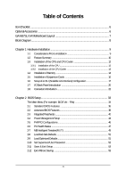
OptionalAccessories ...6 GA-M57SLI-S4 Motherboard Layout 7 Block Diagram ...8 Chapter 1 Hardware Installation 9 1-1 Considerations Prior to Installation 9 1-2 Feature Summary 10 1-3 Installation of the CPU and CPU Cooler 12 1-3-1 Installation of the CPU 12 1-3-2 Installation of the CPU Cooler - Gigabyte GA-M57SLI-S4 | Manual - Page 5
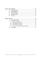
4 Appendix 59 4-1 Unique Software Utilities 59 4-1-1 EasyTune 5 Introduction 59 4-1-2 Xpress Recovery2 Introduction 60 4-1-3 Flash BIOS Method Introduction 62 4-1-4 Configuring SATA Hard Drive(s 66 4-1-5 2- / 4- / 6- / 8- Channel Audio Function Introduction 76 4-2 Troubleshooting 81 - 5 - - Gigabyte GA-M57SLI-S4 | Manual - Page 6
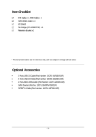
Item Checklist IDE Cable x 1, FDD Cable x 1 SATA 3Gb/s Cable x 4 I/O Shield SLI Bridge (GC-DGBR2-RH) x 1 Retention Bracket x 1 * The items listed above are for reference only, and are subject to change without notice. Optional Accessories Š 2 Ports USB 2.0 - Gigabyte GA-M57SLI-S4 | Manual - Page 7
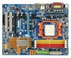
GA-M57SLI-S4 Motherboard Layout KB_MS CPU_FAN ATX_12V ATX SPDIF_O SPDIFO_OPT Socket AM2 COMA LPT PWR_FAN USB 1394 IDE1 Marvell 88E1116 USB LAN1 AUDIO PCIE_12V F_AUDIO PCIE_1 CODEC PCIE_16_1 PCIE_2 SPDIF_I CD_IN PCIE_3 PCIE_16_2 IT8716 PCI1 PCI2 FDD GA-M57SLI-S4 DDRII_1 - Gigabyte GA-M57SLI-S4 | Manual - Page 8
MHz) AMD Socket AM2 CPU CPU CLK+/-(200 MHz) DDRII 800/667/533/400 MHz DIMM Hyper Transport Bus Dual Channel Memory PCI Express x8 PCI Express x16 Marvell 88E1116 LAN RJ45 PCI Express Bus x1 x1 x1 PCIe CLK (100 MHz) 3 PCI Express x1 PCI Bus TSB43AB23 3 IEEE 1394a nVIDIA® nForce 570-SLI BIOS - Gigabyte GA-M57SLI-S4 | Manual - Page 9
instructions below: 1. Please turn off the computer and unplug its power cord. 2. When handling the motherboard, avoid touching any metal leads or connectors. 3. It is best to wear an electrostatic discharge (ESD) cuff when handling electronic components (CPU, RAM motherboard a problem related manual. - Gigabyte GA-M57SLI-S4 | Manual - Page 10
CPU Š Socket AM2 for AMD AthlonTM 64 FX / AthlonTM 64 X2 Dual-Core / AthlonTM 64 / SempronTM processor Front Side Bus Š 2000 MHz Chipset Š nVIDIA® nForce 570-SLI LAN Š Marvell 88E1116 phy (10/100/1000 Mbit) Audio Š Onboard Realtek ALC888 CODEC chip Š Supports High Definition Audio - Gigabyte GA-M57SLI-S4 | Manual - Page 11
system will be less than 4 GB; Windows 64-bit operating system doesn't have such limitation. (Note 2) Whether the CPU Smart FAN Control function is supported will depend on the CPU you install. (Note 3) EasyTune functions may vary depending on different motherboards. - 11 - Hardware Installation - Gigabyte GA-M57SLI-S4 | Manual - Page 12
down on the middle of the CPU and gently press the metal lever back into its original position. Please use extra care when installing the CPU. The CPU will not fit if positioned incorrectly. Rather than applying force, please change the positioning of the CPU. GA-M57SLI-S4 Motherboard - 12 - - Gigabyte GA-M57SLI-S4 | Manual - Page 13
paste on the surface of the CPU. Install all the CPU cooler components (Please refer to the cooler manual for detailed installation instructions). Fig.2 Please connect the CPU cooler power connector to the CPU_FAN connector located on the motherboard so that the CPU cooler can properly function to - Gigabyte GA-M57SLI-S4 | Manual - Page 14
fit in one direction. Insert the DIMM memory module vertically into the DIMM socket. Then push it down. Fig.2 Close the plastic clip at both edges of the DIMM sockets to lock the DIMM module. Reverse the installation steps when you wish to remove the DIMM module. GA-M57SLI-S4 Motherboard - 14 - - Gigabyte GA-M57SLI-S4 | Manual - Page 15
English Dual Channel Memory Configuration The GA-M57SLI-S4 supports the Dual Channel Technology. After operating the Dual Channel Technology, the bandwidth of Memory Bus will double. Due to CPU limitation, if you wish to operate the Dual Channel Technology, follow the guidelines below: 1. Dual - Gigabyte GA-M57SLI-S4 | Manual - Page 16
manual before BIOS Setup. 8. Install related driver motherboard includes a PCIE_12V power connector, which provides extra power to the onboard PCI Express x16 slot. When installing two graphics cards, please connect the power cable from the power supply to this connector. GA-M57SLI-S4 Motherboard - Gigabyte GA-M57SLI-S4 | Manual - Page 17
unit) and the NVIDIA nForce 570-SLI chipset. Together, the NVIDIA SLI technologies work seamlessly to allow two graphics cards to operate in parallel and share the work and deliver heart-pounding PC performance. This section provides instructions on configuring an SLI system. Before you begin - Gigabyte GA-M57SLI-S4 | Manual - Page 18
the two cards, you must install the retention bracket included with the motherboard and secure the retention bracket to the chassis back panel with a screw To enable the SLI function, you must plug the display cable into the graphics card on the PCIE_16_1 slot. GA-M57SLI-S4 Motherboard - 18 - - Gigabyte GA-M57SLI-S4 | Manual - Page 19
menu and then select the Enable SLI multi-GPU checkbox in the SLI multi-GPU dialog box. System will restart after you click Apply. Then the SLI configuration is completed. Note: The SLI configuration screen may differ by driver version. Refer to the user's manual that came with your graphics card - Gigabyte GA-M57SLI-S4 | Manual - Page 20
and hotplug capabilities. Use this port for an IEEE 1394a device. USB port The USB port supports the USB 2.0/1.1 specification. Use this port for USB devices such as an USB keyboard/mouse transmission or receiving is occurring Off LAN link is not established GA-M57SLI-S4 Motherboard - 20 - - Gigabyte GA-M57SLI-S4 | Manual - Page 21
The default Mic in jack. Microphones must be connected to this jack. In addition to the default speakers settings, the ~ audio jacks can be reconfigured to perform different functions via the audio software. Only microphones still MUST be connected to the default Mic In jack ( ). Please refer to the - Gigabyte GA-M57SLI-S4 | Manual - Page 22
1) ATX_12V 2) ATX (Power Connector) 3) PCIE_12V 4) CPU_FAN 5) SYS_FAN 6) PWR_FAN 7) FDD 8) IDE1 9) SATAII1 / 2 / 3 / 4 / 5 / 6 10) BATTERY 11) F_PANEL 12) PWR_LED 13) F_AUDIO 14) CD_IN 15) SPDIF_I 16) F_USB1 / F_USB2 / F_USB3 17) F1_1394 / F2_1394 18) CI 19) CLR_CMOS GA-M57SLI-S4 Motherboard - 22 - Gigabyte GA-M57SLI-S4 | Manual - Page 23
location on the motherboard and connect tightly. The ATX_12V power connector mainly supplies power to the CPU. If the ATX_12V to start. If you use a 24-pin ATX power supply, please remove the small cover on the power connector on the motherboard before plugging in the power cord; otherwise, please - Gigabyte GA-M57SLI-S4 | Manual - Page 24
with color-coded power connector wires CPU damage or system hanging caused by overheating. 1 CPU_FAN CPU_FAN : Pin No. 1 2 3 4 Definition GND +12V / Speed Control Sense Speed Control 1 SYS_FAN 1 PWR_FAN SYS_FAN / PWR_FAN : Pin No. Definition 1 GND 2 +12V 3 Sense GA-M57SLI-S4 Motherboard - Gigabyte GA-M57SLI-S4 | Manual - Page 25
other end of the cable connects to the FDD drive. The types of FDD drives supported are: 360 KB, 720 KB, 1.2 MB, 1.44 MB and 2.88 MB and the other as Slave (for information on settings, please refer to the instructions located on the IDE device). Before attaching the IDE cable, please take note of - Gigabyte GA-M57SLI-S4 | Manual - Page 26
570-SLI) SATA 3Gb/s can provide up to 300 MB/s transfer rate. Please refer to the BIOS setting for the SATA 3Gb/s and install the proper driver in order to work properly. 7 1 SATAII6 SATAII5 SATAII4 Pin No. 1 2 3 4 5 6 7 Definition GND TXP TXN GND RXN RXP GND 1 7 10) BATTERY GA-M57SLI-S4 - Gigabyte GA-M57SLI-S4 | Manual - Page 27
English 11) F_PANEL (Front Panel Jumper) Please connect the power LED, PC speaker, reset switch and power switch etc. of your chassis front panel to the F_PANEL connector according to the pin assignment below. Message LED/ Power/ Sleep LED Power Switch Speaker Connector MSG+ MSG- PW+ PWSPEAK+ - Gigabyte GA-M57SLI-S4 | Manual - Page 28
5 Line Out (R) 6 NC 7 NC 8 No Pin 9 Line Out (L) 10 NC By default, the audio driver is configured to support HD Audio. To connect an AC97 front panel audio module to this connector, please refer to the instructions on page 80 about the software settings. GA-M57SLI-S4 Motherboard - 28 - - Gigabyte GA-M57SLI-S4 | Manual - Page 29
English 14) CD_IN (CD In Connector, black) Connect CD-ROM or DVD-ROM audio out to the connector. Pin No. Definition 1 CD-L 2 GND 3 GND 1 4 CD-R 15) SPDIF_I (S/PDIF In Connector, red) Use S/PDIF In feature only when your device - Gigabyte GA-M57SLI-S4 | Manual - Page 30
1394 cable, please contact your local dealer. Pin No. Definition 2 10 1 9 1 TPA+ 2 TPA- 3 GND 4 GND 5 TPB+ 6 TPB- 7 Power (12V) 8 Power (12V) 9 No Pin 10 GND GA-M57SLI-S4 Motherboard - 30 - - Gigabyte GA-M57SLI-S4 | Manual - Page 31
Intrusion, Case Open) This 2-pin connector allows your system to detect if the chassis cover is removed. You can check the "Case Opened" status in BIOS Setup. Pin No. Definition 1 Signal 1 2 GND 19) CLR_CMOS (Clear CMOS) You may clear the CMOS data to its default values by this header. To - Gigabyte GA-M57SLI-S4 | Manual - Page 32
English GA-M57SLI-S4 Motherboard - 32 - - Gigabyte GA-M57SLI-S4 | Manual - Page 33
by pressing "Ctrl + F1". If you wish to upgrade to a new BIOS, either Gigabyte's Q-Flash or @BIOS utility can be used. Q-Flash allows the user to quickly and easily update or backup BIOS without entering the operating system. @BIOS is a Windows-based utility that does not require users to boot to - Gigabyte GA-M57SLI-S4 | Manual - Page 34
in the BIOS Setup when somehow the system is not stable as usual. This action makes the system reset to the default settings for stability. 3. The BIOS Setup menus described in this chapter are for reference only and may differ from the exact settings for your motherboard. GA-M57SLI-S4 Motherboard - Gigabyte GA-M57SLI-S4 | Manual - Page 35
This setup page includes all the items in standard compatible BIOS. „ Advanced BIOS Features This setup page includes all the items of Award speed, etc. „ MB Intelligent Tweaker(M.I.T.) This setup page is to control CPU clock and frequency ratio. „ Load Fail-Safe Defaults Fail-Safe Defaults indicates - Gigabyte GA-M57SLI-S4 | Manual - Page 36
[None] [None] [None] Drive A Drive B Floppy 3 Mode Support [1.44M, 3.5"] [None] [Disabled] Halt On [All, But Keyboard] Base Memory Extended Memory : Move Enter: Select F5: Previous Values 640K 511M +/-/PU/PD: Value two options are: Large/Auto(default:Auto) GA-M57SLI-S4 Motherboard - 36 - - Gigabyte GA-M57SLI-S4 | Manual - Page 37
3 Mode Support (for Japan memory installed on the motherboard, or 640 KB for systems with 640 KB or more memory installed on the motherboard. Extended Memory The BIOS determines how much extended memory is present during the POST. This is the amount of memory located above 1 MB in the CPU's memory - Gigabyte GA-M57SLI-S4 | Manual - Page 38
Setup Utility-Copyright (C) 1984-2007 Award Software Advanced BIOS Features AMD K8 Cool&Quiet control Hard Disk Boot Priority First Select your boot device priority by USB-HDD. Legacy LAN Select your boot device priority by LAN. Disabled Disable this function. GA-M57SLI-S4 Motherboard - 38 - - Gigabyte GA-M57SLI-S4 | Manual - Page 39
(Default value) Enable Away Mode in Windows XP Media Center operating system. (Away Disabled Disable this function. If you wish to see BIOS POST screen, set this item to "Disabled". Init PCI VGA card and a PCI Express VGA card on the motherboard. PCI Slot PEG Set Init Display First to PCI VGA - Gigabyte GA-M57SLI-S4 | Manual - Page 40
for the first channel of the second SATA controller. (Default value) Disabled Disable the RAID function of this channel. It will operate in ATA mode. GA-M57SLI-S4 Motherboard - 40 - - Gigabyte GA-M57SLI-S4 | Manual - Page 41
On-Chip MAC LAN Disabled Disable the LAN controller built-in core chipset. Auto Enable the LAN controller built-in core chipset. (Default F7: Optimized Defaults This motherboard incorporates cable diagnostic feature designed to detect the status of the attached LAN cable. This feature will - Gigabyte GA-M57SLI-S4 | Manual - Page 42
is the approximate length of the attached LAN cable. When a Cable Problem Occurs... If a cable problem occurs on a specified pair of wires LAN chip. Enabled Disabled Enable this function. Disable this function. (Default value) Onboard Serial Port 1 Auto BIOS will GA-M57SLI-S4 Motherboard - 42 - - Gigabyte GA-M57SLI-S4 | Manual - Page 43
Use DMA to 1. On-Chip USB V1.1+V2.0 V1.1 Enable USB 1.1 and USB 2.0 controllers. (Default value) Enable only USB 1.1 controller Disabled Disable onchip USB support. USB Keyboard Support Enabled Disabled Enable USB keyboard support. Disable USB keyboard support. (Default value) USB Mouse - Gigabyte GA-M57SLI-S4 | Manual - Page 44
Wake Up Modem Ring On USB Resume from Suspend Power-On by Alarm x Day of Month Alarm x Time (hh:mm:ss) Alarm HPET Support type to S3/STR(Suspend To RAM). Soft-Off by Power button wake up system from suspend mode. (Note) Supported on Windows® Vista® operating system only. GA-M57SLI-S4 Motherboard - Gigabyte GA-M57SLI-S4 | Manual - Page 45
. Day of Month Alarm : Everyday, 1~31 Time (hh: mm: ss) Alarm : (0~23) : (0~59) : (0~59) HPET Support (Note) Enabled Enable support for High Precision Event Timer (HPET) funtion. , the system always in "On" state. (Note) Supported on Windows® Vista® operating system only. - 45 - BIOS Setup - Gigabyte GA-M57SLI-S4 | Manual - Page 46
) Set IRQ 3,4,5,7,9,10,11,12,14,15 to PCI 2. Auto assign IRQ to PCI 1. (Default value) Set IRQ 3,4,5,7,9,10,11,12,14,15 to PCI 1. GA-M57SLI-S4 Motherboard - 46 - - Gigabyte GA-M57SLI-S4 | Manual - Page 47
value) CPU/POWER/SYSTEM FAN Fail Warning Disabled Enabled Disable CPU/power/system fan fail warning function. (Default value) Enable CPU/power/system fan fail warning function. (Note) Whether the CPU Smart FAN Control function is supported will depend on the CPU you install. - 47 - BIOS Setup - Gigabyte GA-M57SLI-S4 | Manual - Page 48
. (Default Value) Voltage Set to Voltage when you use a CPU fan with a 3-pin fan power cable. PWM Set to PWM when you use a CPU fan with a 4-pin fan power cable. (Note) Whether the CPU Smart FAN Control function is supported will depend on the CPU you install. GA-M57SLI-S4 Motherboard - 48 - - Gigabyte GA-M57SLI-S4 | Manual - Page 49
Incorrectly doing overclock/overvoltage may result in damage to CPU, chipset, or memory and reduce CPU Frequency (MHz) Allows you to manually set the CPU host frequency. Auto (default) allows BIOS to automatically adjust the CPU host frequency. Important It is highly recommended that the CPU - Gigabyte GA-M57SLI-S4 | Manual - Page 50
as required. The adjustable range is dependent on the CPU being installed. (Default: Normal) Note: Increasing CPU voltage may result in damage to your CPU or reduce the useful life of the CPU. Normal CPU Vcore Displays the normal operating voltage of your CPU. GA-M57SLI-S4 Motherboard - 50 - - Gigabyte GA-M57SLI-S4 | Manual - Page 51
Saving MB Intelligent Tweaker(M.I.T.) Esc: Quit F8: Q-Flash : Select Item F10: Save & Exit Setup F11: Save CMOS to BIOS F12: Load CMOS from BIOS Load Optimized Defaults Selecting this field loads the factory defaults for BIOS and Chipset Features which the system automatically detects. - 51 - Gigabyte GA-M57SLI-S4 | Manual - Page 52
Advance BIOS Features Menu, you will be prompted for the password every time the system is rebooted or any time you try to enter Setup Menu. If you select "Setup" at "Password Check" in Advance BIOS Features Menu, you will be prompted only when you try to enter Setup. GA-M57SLI-S4 Motherboard - 52 - Gigabyte GA-M57SLI-S4 | Manual - Page 53
Health Status Exit Without Saving MB Intelligent Tweaker(M.I.T.) Esc: Quit F8: Q-Flash : Select Item F10: Save & Exit Setup F11: Save CMOS to BIOS F12: Load CMOS from BIOS Save Data to CMOS Type "Y" will quit the Setup Utility and save the user setup value to RTC CMOS. Type "N" will return to - Gigabyte GA-M57SLI-S4 | Manual - Page 54
English GA-M57SLI-S4 Motherboard - 54 - - Gigabyte GA-M57SLI-S4 | Manual - Page 55
to install other drivers. • After the drivers are installed, follow the onscreen instructions to restart your system. You can install other applications included in the CD-ROM. • For USB 2.0 driver support under the Windows XP operating system, please install the Windows XP Service Pack 1 or later - Gigabyte GA-M57SLI-S4 | Manual - Page 56
Applications This page displays all the tools that Gigabyte developed and some free software, you can choose anyone you want and press "install" to install them. 3-3 Driver CD Information This page lists the contents of software and drivers in this CD-title. GA-M57SLI-S4 Motherboard - 56 - - Gigabyte GA-M57SLI-S4 | Manual - Page 57
English 3-4 Hardware Information This page lists all device you have for this motherboard. 3-5 Contact Us Please see the last page for details. - 57 - Drivers Installation - Gigabyte GA-M57SLI-S4 | Manual - Page 58
English GA-M57SLI-S4 Motherboard - 58 - - Gigabyte GA-M57SLI-S4 | Manual - Page 59
yet easy to use tools such as 1) Overclocking for enhancing system performance, 2) C.I.A. and M.I.B. for special enhancement for CPU and Memory, 3) Smart-Fan control for managing fan speed control of both CPU cooling fan and North-Bridge Chipset cooling fan, 4) PC health for monitoring system - Gigabyte GA-M57SLI-S4 | Manual - Page 60
memory 3. VESA-supported VGA cards How to use the Xpress Recovery2 Initial access by booting from CD-ROM and subsequent access by pressing the F9 key: Steps: After entering BIOS Setup, go to Advanced BIOS of OS and all required drivers as well as software. GA-M57SLI-S4 Motherboard - 60 - - Gigabyte GA-M57SLI-S4 | Manual - Page 61
Windows 2000, be sure to execute the EnableBigLba.exe program from the driver CD before data backup. 2. It is normal that data backup takes longer time than data restoration. 3. Xpress Recovery2 is compliant with the GPL regulations. 4. On a few motherboards based on Nvidia chipsets, BIOS update - Gigabyte GA-M57SLI-S4 | Manual - Page 62
Floppy A" and press ENTER. Q-Flash Utility v2.02 Flash Type/Size PMC 25LV040 512K Keep DMI Data Enable Update BIOS from Drive Sa0vefilBeI(Os)SfotounDdrive EnteFr l:oRppuyn A :Move ESC:Reset :Power Off HDD 0-0 Total size : 0 GA-M57SLI-S4 Motherboard Free size : 0 - 62 - - Gigabyte GA-M57SLI-S4 | Manual - Page 63
press ENTER. Make sure again the BIOS file matches your motherboard model. Step 2: The process of system reading the BIOS file from the floppy disk is displayed on the screen. When the message "Are you sure to update BIOS?" appears, press ENTER. The BIOS update will begin and the current process - Gigabyte GA-M57SLI-S4 | Manual - Page 64
Update" icon b. Click "Update New BIOS" c. Please select "All Files" in dialog box while opening the old file. d. Please search for BIOS unzip file, downloading from internet or any other methods (such as: M57SLS42.FA). e. Complete update process following the instruction. GA-M57SLI-S4 Motherboard - Gigabyte GA-M57SLI-S4 | Manual - Page 65
II, be sure that motherboard's model name in BIOS unzip file are the same as your motherboard's. Otherwise, your system won't boot. III. In method I, if the BIOS file you need cannot be found in @BIOSTM server, please go onto Gigabyte's web site for downloading and updating it according to method - Gigabyte GA-M57SLI-S4 | Manual - Page 66
formatted floppy disk. (Note) (c) Windows XP/2000 setup disk. (d) Driver CD for your motherboard. (Note) (1) Installing SATA hard drive motherboard. Then connect the power connector from your power supply to the hard drive. (Note) Required for setting up RAID array. GA-M57SLI-S4 Motherboard - - Gigabyte GA-M57SLI-S4 | Manual - Page 67
Config On-Chip IDE Channel0 On-Chip MAC Lan NV Serial-ATA Controller IDE Prefetch Moed Onboard Audio Function SMART LAN Onboard 1394 Onboard LAN Boot ROM Onboard Serial Port 1 Onboard Parallel Port Parallel Port Mode x ECP Mode Use DMA On-Chip USB USB Keyboard Support USB Mouse Support Legacy USB - Gigabyte GA-M57SLI-S4 | Manual - Page 68
] [Setup] [Disabled] [Disabled] [Enabled] [PEG] Item Help Menu Level : Move Enter: Select F5: Previous Values Step 3: Save and exit BIOS Setup. +/-/PU/PD: Value F10: Save F6: Fail-Safe Defaults Figure 3 ESC: Exit F1: General Help F7: Optimized Defaults GA-M57SLI-S4 Motherboard - 68 - - Gigabyte GA-M57SLI-S4 | Manual - Page 69
BIOS Enter the RAID BIOS setup utility to configure a RAID array. Skip this step and proceed to Section 4 if you do not want to create RAID. Step 1: After the POST memory a RAID mode. The supported RAID modes include Mirroring, Striping) is selected, you can manually set the striping block size. - Gigabyte GA-M57SLI-S4 | Manual - Page 70
]a11tNa..01O?..MM ST3120026AS ST3120026AS [Y] YES [N] NO [ ] Del Capacity 111.79GB 111.79GB [ESC] Quit [F6] Back [F7] Finish [TAB] Navigate [ ] Select [ENTER] Popup Figure 7 GA-M57SLI-S4 Motherboard - 70 - - Gigabyte GA-M57SLI-S4 | Manual - Page 71
Nvidia RAID utility, press ESC in the main menu or Ctrl+X in the Array List screen. Now, you can proceed to install the SATA controller driver and operating system. - 71 - Appendix - Gigabyte GA-M57SLI-S4 | Manual - Page 72
a startup disk: Use an alternative system and insert the GIGABYTE motherboard driver CD-ROM. From the CD-ROM drive folder, double click the MENU.exe file in the BootDrv folder (Figure 12). A command prompt window will open similar to that in Figure 11. GA-M57SLI-S4 Motherboard Figure 12 - 72 - - Gigabyte GA-M57SLI-S4 | Manual - Page 73
the floppy disk containing the SATA driver and press S (Figure 14). Windows Setup Setup could not determine the type of one or more mass storage devices installed in your system, or you have chosen to manually specify an adapter. Currently, Setup will load support for the following mass storage - Gigabyte GA-M57SLI-S4 | Manual - Page 74
for use with Windows, press ENTER. S=Specify Additional Device ENTER=Continue F3=Exit Figure 16 If a message appears saying one or some file(s) cannot be found, please check the floppy disk or copy the correct SATA driver again from the motherboard driver CD. GA-M57SLI-S4 Motherboard - 74 - - Gigabyte GA-M57SLI-S4 | Manual - Page 75
(Figure 17) appears, press ENTER to continue the SATA driver installation from the floppy disk. Windows Setup Setup will load support for the following mass storage device(s): NVIDIA RAID CLASS DRIVER (required) NVIDIA NForce Storage Controller (required) * To specify additional SCSI adapters, CD - Gigabyte GA-M57SLI-S4 | Manual - Page 76
capability supported by HD Audio allows users to change the function for each audio jack by the audio audio driver, you should find an Audio Manager icon in your system tray (you can also find the icon in Control Panel). Doubleclick the icon to open the Audio Control Panel. GA-M57SLI-S4 Motherboard - Gigabyte GA-M57SLI-S4 | Manual - Page 77
Line Out jack, a small window will pop up and ask you what type of equipment is connected. Choose Headphone or Line Out depending on the device connected and click OK. The 2-channel audio setup is completed. 4 Channel Audio Setup STEP 1 : After installation of the audio driver, you should find an - Gigabyte GA-M57SLI-S4 | Manual - Page 78
you what type of equipment is connected. Choose a device depending on the type of speaker connected (6-channel audio consists of Front Speaker Out (Line Out), Rear Speaker Out, and Center/Subwoofer Speaker Out) then click OK. The 6-channel audio setup is completed. GA-M57SLI-S4 Motherboard - 78 - - Gigabyte GA-M57SLI-S4 | Manual - Page 79
Setup STEP 1 : After installation of the audio driver, you should find an Audio Manager icon in your system tray (you can also find the icon in Control Panel). Doubleclick the icon to open the Audio Control Panel. STEP 2: In the Audio Control Panel, click the Audio I/O tab. In the upper left list - Gigabyte GA-M57SLI-S4 | Manual - Page 80
panel audio connector to support AC97 Audio mode, go to the Audio Control Panel and click the Audio I/O tab. In the ANALOG area, click the Tool icon and then select the Disable front panel jack detection check box. This action completes the AC'97 Audio configuration. GA-M57SLI-S4 Motherboard - 80 - Gigabyte GA-M57SLI-S4 | Manual - Page 81
English 4-2 Troubleshooting Below is a collection of general asked questions. To check general asked questions based on a specific motherboard model, please log on to GIGABYTE's website. Question 1: I cannot see some options that were included in previous BIOS after updating BIOS. Why? Answer: Some - Gigabyte GA-M57SLI-S4 | Manual - Page 82
English GA-M57SLI-S4 Motherboard - 82 - - Gigabyte GA-M57SLI-S4 | Manual - Page 83
- 83 - Appendix English - Gigabyte GA-M57SLI-S4 | Manual - Page 84
English GA-M57SLI-S4 Motherboard - 84 - - Gigabyte GA-M57SLI-S4 | Manual - Page 85
- 85 - Appendix English - Gigabyte GA-M57SLI-S4 | Manual - Page 86
TEL: +86-24-83992901 FAX: +86-24-83992909 India GIGABYTE TECHNOLOGY (INDIA) LIMITED WEB address : http://www.giga-byte.co.in/ Saudi Arabia WEB address : http://www.gigabyte.com.sa Australia GIGABYTE TECHNOLOGY PTY. LTD. WEB address : http://www.gigabyte.com.au GA-M57SLI-S4 Motherboard - 86 - - Gigabyte GA-M57SLI-S4 | Manual - Page 87
Technology Co., Ltd. in SERBIA & MONTENEGRO WEB address : http://www.gigabyte.co.yu You may go to the GIGABYTE website, select your language in the language list on the top right corner of the website. GIGABYTE Global Service System To submit a technical or non-technical (Sales/ Marketing) question - Gigabyte GA-M57SLI-S4 | Manual - Page 88
- 88 -
-
 1
1 -
 2
2 -
 3
3 -
 4
4 -
 5
5 -
 6
6 -
 7
7 -
8
-
9
-
10
-
11
-
12
-
13
-
14
-
15
-
16
-
17
-
18
-
19
-
20
-
21
-
22
-
23
-
24
-
25
-
26
-
27
-
28
-
29
-
30
-
31
-
32
-
33
-
34
-
35
-
36
-
37
-
38
-
39
-
40
-
41
-
42
-
43
-
44
-
45
-
46
-
47
-
48
-
49
-
50
-
51
-
52
-
53
-
54
-
55
-
56
-
57
-
58
-
59
-
60
-
61
-
62
-
63
-
64
-
65
-
66
-
67
-
68
-
69
-
70
-
71
-
72
-
73
-
74
-
75
-
76
-
77
-
78
-
79
-
80
-
81
-
82
-
83
-
84
-
85
-
86
-
87
-
88
 |
 |

GA-M57SLI-S4
AMD Athlon
TM
64 FX / Athlon
TM
64 X2 Dual-Core /
AMD Athlon
TM
64 / Sempron
TM
AM2 Processor Motherboard
User's Manual
Rev. 2002
12ME-M57SLI4R-2002R
*
The WEEE marking on the product indicates this product must not be disposed of with user's other household waste
and must be handed over to a designated collection point for the recycling of waste electrical and electronic equipment!!
*
The WEEE marking applies only in European Union's member states.