Gigabyte GA-MA74GMT-S2 Manual - Page 27
F_USB1/F_USB2 USB Headers, SPDIF_IO S/PDIF In/Out Header
 |
View all Gigabyte GA-MA74GMT-S2 manuals
Add to My Manuals
Save this manual to your list of manuals |
Page 27 highlights
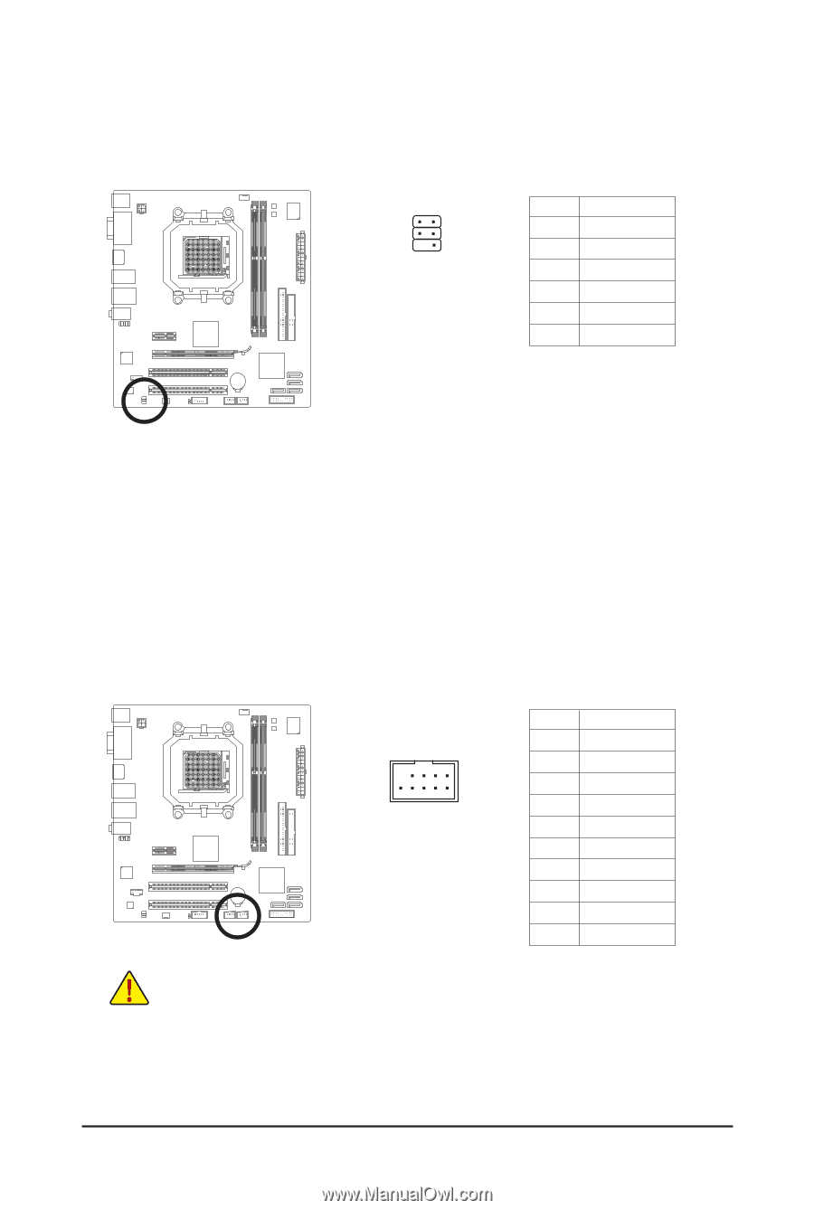
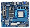
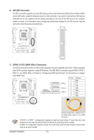
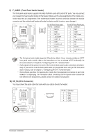
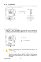
11) SPDIF_IO (S/PDIF In/Out Header) This header supports digital S/PDIF In/Out. Via an optional S/PDIF In and Out cable, this header can connect to an audio device that supports digital audio out and an audio system that supports digital audio in. For purchasing the optional S/PDIF In and Out cable, please contact the local dealer. 6 5 2 1 Pin No. 1 2 3 4 5 6 Definition Power No Pin SPDIF SPDIFI GND GND 12) F_USB1/F_USB2 (USB Headers) The headers conform to USB 2.0/1.1 specification. Each USB header can provide two USB ports via an optional USB bracket. For purchasing the optional USB bracket, please contact the local dealer. Pin No. Definition 1 Power (5V) 2 Power (5V) 9 10 1 2 3 USB DX- 4 USB DY- 5 USB DX+ 6 USB DY+ 7 GND 8 GND 9 No Pin 10 NC • Do not plug the IEEE 1394 bracket (2x5-pin) cable into the USB header. • Prior to installing the USB bracket, be sure to turn off your computer and unplug the power cord from the power outlet to prevent damage to the USB bracket. - 27 - Hardware Installation
-
 1
1 -
2
-
3
-
4
-
5
-
6
-
7
-
8
-
9
-
10
-
11
-
12
-
13
-
14
-
15
-
16
-
17
-
18
-
19
-
20
-
21
-
 22
22 -
 23
23 -
 24
24 -
 25
25 -
 26
26 -
 27
27 -
 28
28 -
 29
29 -
 30
30 -
 31
31 -
 32
32 -
33
-
34
-
35
-
36
-
37
-
38
-
39
-
40
-
41
-
42
-
43
-
44
-
45
-
46
-
47
-
48
-
49
-
50
-
51
-
52
-
53
-
54
-
55
-
56
-
57
-
58
-
59
-
60
-
61
-
62
-
63
-
64
-
65
-
66
-
67
-
68
-
69
-
70
-
71
-
72
-
73
-
74
-
75
-
76
-
77
-
78
-
79
-
80
-
81
-
82
-
83
-
84
-
85
-
86
-
87
-
88
-
89
-
90
-
91
-
92
-
93
-
94
-
95
-
96
-
97
-
98
-
99
-
100
 |
 |