Gigabyte GA-MA78LMT-US2H Manual - Page 42
RAS to RAS Delay
 |
View all Gigabyte GA-MA78LMT-US2H manuals
Add to My Manuals
Save this manual to your list of manuals |
Page 42 highlights
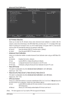
Trfc3 for DIMM4 Options are: Auto (default), 90ns, 110ns, 160ns, 300ns, 350ns. Write Recovery Time Options are: Auto (default), 5T~8T, 10T, 12T. Precharge Time Options are: Auto (default), 4T~7T. Row Cycle Time Options are: Auto (default), 11T~42T. RAS to RAS Delay Options are: Auto (default), 4T~7T. Bank Interleaving Enables or disables memory bank interleaving. Enabled allows the system to simultaneously access different banks of the memory to increase memory performance and stability. (Default: Enabled) Channel interleave Enables or disables memory channel interleaving. Enabled allows the system to simultaneously access different channels of the memory to increase memory performance and stability. (Default: Enabled) ******** System Voltage Optimized ******** System Voltage Control Determines whether to manually set the system voltages. Auto lets the BIOS automatically set the system voltages as required. Manual allows all voltage control items below to be configurable. (Default: Manual) DDR3 Voltage Control Allows you to set memory voltage. Normal Supplies the memory voltage as required. (Default) +0.050V ~ +0.750V The adjustable range is from +0.050V to +0.750V. Note: Increasing memory voltage may result in damage to the memory. NorthBridge Volt Control Allows you to set the North Bridge voltage. Normal Supplies the North Bridge voltage as required. (Default) +0.1V ~ +0.3V The adjustable range is from +0.1V to +0.3V. SouthBridge Volt Control Allows you to set the South Bridge voltage. Normal Supplies the South Bridge voltage as required. (Default) +0.1V ~ +0.3V The adjustable range is from +0.1V to +0.3V. BIOS Setup - 42 -
-
 1
1 -
2
-
3
-
4
-
5
-
6
-
7
-
8
-
9
-
10
-
11
-
12
-
13
-
14
-
15
-
16
-
17
-
18
-
19
-
20
-
21
-
22
-
23
-
24
-
25
-
26
-
27
-
28
-
29
-
30
-
31
-
32
-
33
-
34
-
35
-
36
-
 37
37 -
 38
38 -
 39
39 -
 40
40 -
 41
41 -
 42
42 -
 43
43 -
 44
44 -
 45
45 -
 46
46 -
 47
47 -
48
-
49
-
50
-
51
-
52
-
53
-
54
-
55
-
56
-
57
-
58
-
59
-
60
-
61
-
62
-
63
-
64
-
65
-
66
-
67
-
68
-
69
-
70
-
71
-
72
-
73
-
74
-
75
-
76
-
77
-
78
-
79
-
80
-
81
-
82
-
83
-
84
-
85
-
86
-
87
-
88
-
89
-
90
-
91
-
92
-
93
-
94
-
95
-
96
-
97
-
98
-
99
-
100
-
101
-
102
-
103
-
104
 |
 |
