Gigabyte GA-MA790GPT-UD3H Manual - Page 22
Optical S/PDIF Out Connector, IEEE 1394a Port, RJ-45 LAN Port, A. Dual Display Configurations - software
 |
UPC - 818313008343
View all Gigabyte GA-MA790GPT-UD3H manuals
Add to My Manuals
Save this manual to your list of manuals |
Page 22 highlights
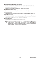
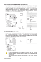
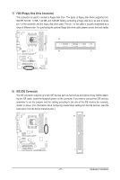
A. Dual Display Configurations: This motherboard provides three ports for video output: DVI-D, HDMI and D-Sub. The table below shows the supported dual display configurations. Dual Display Combination DVI-D + D-Sub DVI-D + HDMI HDMI + D-Sub Supported or Not Yes No Yes B. Playback of HD DVD and Blu-ray Discs: In order to get better playback quality, when playing the HD DVD or Blu-ray discs, refer to the recommended system requirements (or better) below. • Memory: Two 1 GB DDR3 1066 MHz memory modules with dual channel mode enabled • BIOS Setup: At least 256 MB of UMA Frame Buffer Size (refer to Chapter 2, "BIOS Setup," "Advanced BIOS Features," for more information) • Playback software: CyberLink PowerDVD 8.0 or later (Note: Please ensure Hardware Acceleration is enabled.) • HDCP compliant monitor(s) Optical S/PDIF Out Connector This connector provides digital audio out to an external audio system that supports digital optical audio. Before using this feature, ensure that your audio system provides an optical digital audio in connector. IEEE 1394a Port The IEEE 1394 port supports the IEEE 1394a specification, featuring high speed, high bandwidth and hotplug capabilities. Use this port for an IEEE 1394a device. RJ-45 LAN Port The Gigabit Ethernet LAN port provides Internet connection at up to 1 Gbps data rate. The following describes the states of the LAN port LEDs. Connection/ Speed LED Activity LED LAN Port Connection/Speed LED: State Description Orange 1 Gbps data rate Green 100 Mbps data rate Off 10 Mbps data rate Activity LED: State Description Blinking Data transmission or receiving is occurring Off No data transmission or receiving is occurring • When removing the cable connected to a back panel connector, first remove the cable from your device and then remove it from the motherboard. • When removing the cable, pull it straight out from the connector. Do not rock it side to side to prevent an electrical short inside the cable connector. Hardware Installation - 22 -
-
 1
1 -
2
-
3
-
4
-
5
-
6
-
7
-
8
-
9
-
10
-
11
-
12
-
13
-
14
-
15
-
16
-
 17
17 -
 18
18 -
 19
19 -
 20
20 -
 21
21 -
 22
22 -
 23
23 -
 24
24 -
 25
25 -
 26
26 -
 27
27 -
28
-
29
-
30
-
31
-
32
-
33
-
34
-
35
-
36
-
37
-
38
-
39
-
40
-
41
-
42
-
43
-
44
-
45
-
46
-
47
-
48
-
49
-
50
-
51
-
52
-
53
-
54
-
55
-
56
-
57
-
58
-
59
-
60
-
61
-
62
-
63
-
64
-
65
-
66
-
67
-
68
-
69
-
70
-
71
-
72
-
73
-
74
-
75
-
76
-
77
-
78
-
79
-
80
-
81
-
82
-
83
-
84
-
85
-
86
-
87
-
88
-
89
-
90
-
91
-
92
-
93
-
94
-
95
-
96
-
97
-
98
-
99
-
100
-
101
-
102
-
103
-
104
 |
 |
