Gigabyte GA-N650SLI-DS4 Manual
Gigabyte GA-N650SLI-DS4 Manual
 |
UPC - 818313003348
View all Gigabyte GA-N650SLI-DS4 manuals
Add to My Manuals
Save this manual to your list of manuals |
Gigabyte GA-N650SLI-DS4 manual content summary:
- Gigabyte GA-N650SLI-DS4 | Manual - Page 1
GA-N650SLI-DS4 Intel® CoreTM 2 Extreme quad-core / CoreTM 2 Quad / Intel® CoreTM 2 Extreme dual-core / CoreTM 2 Duo / Intel® Pentium® Processor Extreme Edition / Intel® Pentium® D / Pentium® 4 / Celeron® D LGA775 Processor Motherboard User's Manual Rev. 1002 12ME-N650DS4-1002R * The WEEE marking on - Gigabyte GA-N650SLI-DS4 | Manual - Page 2
Motherboard GA-N650SLI-DS4 March 15, 2007 Motherboard GA-N650SLI-DS4 March 15, 2007 - Gigabyte GA-N650SLI-DS4 | Manual - Page 3
Copyright © 2007 GIGA-BYTE TECHNOLOGY CO., LTD. All rights reserved. The trademarks mentioned in the manual are legally registered to their respective companies. Notice The written content provided with this product is the property of Gigabyte. No part of this manual may be reproduced, copied, - Gigabyte GA-N650SLI-DS4 | Manual - Page 4
...6 GA-N650SLI-DS4 Motherboard Layout 7 Block Diagram ...8 Chapter 1 Hardware Installation 9 1-1 Considerations Prior to Installation 9 1-2 Feature Summary 10 1-3 Installation of the CPU and CPU Cooler 12 1-3-1 Installation of the CPU 12 1-3-2 Installation of the CPU Cooler - Gigabyte GA-N650SLI-DS4 | Manual - Page 5
58 3-3 Driver CD Information 58 3-4 Hardware Information 59 3-5 Contact Us ...59 3-6 Windows Vista ReadyBoost 60 Chapter 4 Appendix 61 4-1 Unique Software Utilities 61 4-1-1 EasyTune 5 Introduction 61 4-1-2 Xpress Recovery2 Introduction 62 4-1-3 Flash BIOS Method Introduction - Gigabyte GA-N650SLI-DS4 | Manual - Page 6
Item Checklist IDE Cable x 1 and FDD Cable x 1 SATA 3Gb/s Cable x 4 I/O Shield x 1 SLI Bridge (GC-DGBR2-RH) x 1 Retention Bracket x 1 * The items listed above are for reference only, and are subject to change without notice. Optional Accessories Š 2 Ports USB 2.0 - Gigabyte GA-N650SLI-DS4 | Manual - Page 7
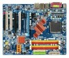
GA-N650SLI-DS4 Motherboard Layout COMA LPT KB_MS COAXIAL OPTICAL ATX_12V_2X LGA775 CPU_FAN ATX PWR_FAN USB 1394 GA-N650SLI-DS4 USB LAN F_AUDIO AUDIO Marvell 88E1116 PCIE_1 nVIDIA® nForce 650i SLI NB_FAN PCIE_16_1 IDE2 IDE1 DDRII1 DDRII2 DDRII3 DDRII4 SYS_FAN CODEC PCIE_2 PCI1 - Gigabyte GA-N650SLI-DS4 | Manual - Page 8
Processor CPU CLK+/-(333/266/200/133 MHz) Host Interface nVIDIA® nForce 650i SLI Northbridge DDRII 800/667/533 MHz DIMM Dual Channel Memory LAN RJ45 Marvell 88E1116 2 PCI Express x 1 PCI Bus TSB43AB23 nVIDIA® nForce 650i SLI Southbridge 4 SATA 3Gb/s ATA 33/66/100/133 IDE Channels Dual BIOS - Gigabyte GA-N650SLI-DS4 | Manual - Page 9
instructions below: 1. Please turn off the computer and unplug its power cord. 2. When handling the motherboard, avoid touching any metal leads or connectors. 3. It is best to wear an electrostatic discharge (ESD) cuff when handling electronic components (CPU, RAM motherboard a problem related manual. - Gigabyte GA-N650SLI-DS4 | Manual - Page 10
CPU Š LGA775 for Intel® CoreTM 2 Extreme quad-core/CoreTM 2 Extreme dual-core/ CoreTM 2 Quad/CoreTM 2 Duo/Pentium® processor Extreme Edition/ Pentium® D/Pentium® 4/Celeron® D Front Side Bus Š L2 cache varies with CPU Š Supports 1333/1066/800/533 MHz FSB Chipset Š nVIDIA® nForce 650i SLI - Gigabyte GA-N650SLI-DS4 | Manual - Page 11
warning Š CPU/System Smart Fan Control BIOS Š 2 4 Mbit flash ROM Š Use of licensed AWARD BIOS Š Supports Dual BIOS Š PnP 1.0a, DMI 2.0, SM BIOS 2.3, ACPI 1.0b Additional Features Š Supports @BIOS Š Supports Download Center Š Supports Q-Flash Š Supports EasyTune (Note 3) Š Supports Xpress - Gigabyte GA-N650SLI-DS4 | Manual - Page 12
- CPU: An Intel® Pentium 4 CPU with HT Technology - Chipset: A chipset that supports HT Technology - BIOS: A BIOS that supports HT Technology and that might cause damage to the CPU during installation.) GA-N650SLI-DS4 Motherboard - 12 - Fig. 4 Once the CPU is properly inserted, please replace the - Gigabyte GA-N650SLI-DS4 | Manual - Page 13
make sure the Male and Female push pin are joined closely. (for detailed installation instructions, please refer to the CPU cooler installation section of the user manual) Fig. 5 Please check the back of motherboard after installing. If the push pin is inserted as the picture, the installation is - Gigabyte GA-N650SLI-DS4 | Manual - Page 14
insert the module, please switch the direction. The motherboard supports DDRII memory modules, whereby BIOS will automatically detect memory capacity and specifications. Memory modules are designed so that they can steps when you wish to remove the DIMM module. GA-N650SLI-DS4 Motherboard - 14 - - Gigabyte GA-N650SLI-DS4 | Manual - Page 15
. The GA-N650SLI-DS4 includes 4 DIMM sockets, and each Channel has two DIMM sockets as following: Channel 0 : DDRII1, DDRII2 Channel 1 : DDRII3, DDRII4 If you want to operate the Dual Channel Technology, please note the following explanations due to the limitation of Intel chipset specifications - Gigabyte GA-N650SLI-DS4 | Manual - Page 16
outlined below: 1. Read the related expansion card's instruction document before install the expansion card into the computer the computer, if necessary, setup BIOS utility of expansion card from BIOS. 8. Install related driver from the operating system. Installing GA-N650SLI-DS4 Motherboard - 16 - - Gigabyte GA-N650SLI-DS4 | Manual - Page 17
nVIDIA® nForce 650i SLI chipset. Together, the nVIDIA® SLI technologies work seamlessly to allow two graphics cards to operate in parallel and share the work and deliver heart-pounding PC performance. This section introduces steps to configure an SLI system on the GA-N650SLI-DS4 motherboard. Before - Gigabyte GA-N650SLI-DS4 | Manual - Page 18
slots on the bridge connector securely fit onto the SLI gold edge connetors. Female slots on the bridge connector motherboard and secure the retention bracket to the chassis back panel with a screw. Place this section on the top of the bridge connector. retention bracket GA-N650SLI-DS4 Motherboard - Gigabyte GA-N650SLI-DS4 | Manual - Page 19
BIOS Driver Setting: Step 1: After installing graphics card driver SLI multi-GPU checkbox in the SLI multi-GPU dialog box. System will restart after you click Apply. Then the SLI configuration is completed. (Note) For more information about software configurations for SLI, refer to the user's manual - Gigabyte GA-N650SLI-DS4 | Manual - Page 20
USB interface. Also make sure your OS supports USB controller. If your OS does not support USB controller, please contact OS vendor for possible patch or driver upgrade. For more information please contact your ROM, walkman etc. can be connected to Line In jack. GA-N650SLI-DS4 Motherboard - 20 - - Gigabyte GA-N650SLI-DS4 | Manual - Page 21
. Microphone must be connected to MIC In jack. In addition to the default speakers settings, the ~ audio jacks can be reconfigured to perform different functions via the audio software. Only microphones still MUST be connected to the default Mic In jack ( ). Please refer to the 2-/4-/6-/8- channel - Gigabyte GA-N650SLI-DS4 | Manual - Page 22
on the motherboard and connect tightly. The ATX 12V (2x4-pin) power connector mainly supplies power to the CPU. If the 3 4 5 6 7 8 Definition GND GND GND GND +12V +12V +12V +12V 12 24 1 13 ATX GA-N650SLI-DS4 Motherboard Pin No. 1 2 3 4 5 6 7 8 9 10 11 12 Definition 3.3V 3.3V GND +5V GND - Gigabyte GA-N650SLI-DS4 | Manual - Page 23
power voltage. The black connector wire is the ground wire (GND). Please remember to connect the CPU/system fan cable to the CPU_FAN/SYS_FAN connector to prevent the CPU/system from overheating and failure. 1 CPU_FAN 1 SYS_FAN 1 PWR_FAN CPU_FAN/SYS_FAN: Pin No. Definition 1 GND 2 +12V/Speed - Gigabyte GA-N650SLI-DS4 | Manual - Page 24
FDD cable while the other end of the cable connects to the FDD drive. The types of FDD drives supported are: 360 KB, 720 KB, 1.2 MB, 1.44 MB and 2.88 MB. Before attaching the FDD cable, please take note of the foolproof groove in the FDD connector. 33 1 34 2 GA-N650SLI-DS4 Motherboard - 24 - - Gigabyte GA-N650SLI-DS4 | Manual - Page 25
as Slave (for information on settings, please refer to the instructions located on the IDE device). Before attaching the IDE cable, up to 300 MB/s transfer rate. Please refer to the BIOS setting for the Serial ATA and install the proper driver in order to work properly. SATAII0 7 1 SATAII2 7 - Gigabyte GA-N650SLI-DS4 | Manual - Page 26
1: Power Pin 2- Pin 3: NC Pin 4: Data(-) Open: Normal Close: Reset Hardware System Open: Normal Close: Power On/Off Pin 1: LED anode(+) Pin 2: LED cathode(-) NC GA-N650SLI-DS4 Motherboard - 26 - - Gigabyte GA-N650SLI-DS4 | Manual - Page 27
5 Line Out (R) 6 NC 7 NC 8 No Pin 9 Line Out (L) 10 NC By default, the audio driver is configured to support HD Audio. To connect an AC97 front panel audio module to this connector, please refer to the instructions on Page 85 about the software settings. - 27 - Hardware Installation - Gigabyte GA-N650SLI-DS4 | Manual - Page 28
1 MPD+ 2 MPD- 3 MPD- 14) CD_IN (CD IN) Connect CD-ROM or DVD-ROM audio out to the connector. Pin No. Definition 1 CD-L 2 GND 3 GND 1 4 CD-R GA-N650SLI-DS4 Motherboard - 28 - - Gigabyte GA-N650SLI-DS4 | Manual - Page 29
English 15) SPDIF_IN (S/PDIF In Connector) Use S/PDIF IN feature only when your device has digital output function. Be careful with the polarity of the SPDIF_I connector. Check the pin assignment carefully while you connect the S/PDIF cable, incorrect connection between the cable and connector will - Gigabyte GA-N650SLI-DS4 | Manual - Page 30
Intrusion, Case Open) This 2-pin connector allows your system to detect if the chassis cover is removed. You can check the "Case Opened" status in BIOS Setup. Pin No. Definition 1 Signal 1 2 GND GA-N650SLI-DS4 Motherboard - 30 - - Gigabyte GA-N650SLI-DS4 | Manual - Page 31
is incorrectly replaced. Replace only with the same or equivalent type recommended by the manufacturer. Dispose of used batteries according to the manufacturer's instructions. If you want to erase CMOS... 1. Turn off the computer and unplug the power cord. 2. Gently take out the battery and put it - Gigabyte GA-N650SLI-DS4 | Manual - Page 32
English GA-N650SLI-DS4 Motherboard - 32 - - Gigabyte GA-N650SLI-DS4 | Manual - Page 33
pressing "Ctrl + F1". If you wish to upgrade to a new BIOS, either Gigabyte's Q-Flash or @BIOS utility can be used. Q-Flash allows the user to quickly and easily update or backup BIOS without entering the operating system. @BIOS is a Windows-based utility that does not require users to boot to DOS - Gigabyte GA-N650SLI-DS4 | Manual - Page 34
key to enter BIOS Setup program. : Xpress Recovery2 Press the F9 key to enter the Xpress Recovery2 screen. : Boot Menu Press the F12 key to enter Boot Menu to select the first boot device. : Qflash Press the End key to enter Q-Flash utility. GA-N650SLI-DS4 Motherboard - 34 - - Gigabyte GA-N650SLI-DS4 | Manual - Page 35
menus described in this chapter are for reference only and may differ from the exact settings for your motherboard. BIOS Setting Recovery F11 : Save CMOS to BIOS This function allows you to make a record of the current CMOS settings as a profile. You can create up to 8 profiles (Profile 1-8) and - Gigabyte GA-N650SLI-DS4 | Manual - Page 36
Tweaker(M.I.T.) This setup page is control CPU clock and frequency ratio. „ the value of the system parameters which the system would be in best performance configuration. „ Set Supervisor Password Change, set, or disable password. It value changes and exit setup. GA-N650SLI-DS4 Motherboard - 36 - - Gigabyte GA-N650SLI-DS4 | Manual - Page 37
None] [None] [None] Drive A Floppy 3 Mode Support Halt On Base Memory Extended Memory [1.44M, 3.5"] [Disabled The week, from Sun to Sat, determined by the BIOS and is display-only Month The month, Jan. Through faster system start up. • Manual User can manually input the correct settings. Access - Gigabyte GA-N650SLI-DS4 | Manual - Page 38
Support motherboard, or 640 K for systems with 640 K or more memory installed on the motherboard. Extended Memory The BIOS determines how much extended memory is present during the POST. This is the amount of memory located above 1 MB in the CPU's memory address map. GA-N650SLI-DS4 Motherboard - Gigabyte GA-N650SLI-DS4 | Manual - Page 39
CPUID Max. to 3 (Note) No-Execute Memory Protect (Note) CPU Enhanced Halt (C1E) (Note) CPU Thermal Monitor 2(TM2) (Note) CPU EIST Function (Note) Virtualization Technology (Note) Full Screen LOGO Show Robust Graphics Booster x VGA Core Clock Init Display First [Press Enter] [Floppy] [Hard Disk - Gigabyte GA-N650SLI-DS4 | Manual - Page 40
CPU Thermal Monitor 2 (TM2) function. CPU EIST Function (Note) Enabled Enable CPU EIST function. (Default value) Disabled Disable CPU EIST function. Virtualization Technology (Note) Enabled Enable Virtualization Technology that supports this function. GA-N650SLI-DS4 Motherboard - 40 - - Gigabyte GA-N650SLI-DS4 | Manual - Page 41
On-Chip IDE Channel1 NV Serial-ATA Controller IDE Prefetch Mode On-Chip USB USB Keyboard Support USB Mouse Support Onboard Audio Function SMART LAN Onboard 1394 Legacy USB storage detect Onboard Serial Port 1 3Gb/s controller. (Default value) Disabled Disable this function. - 41 - BIOS Setup - Gigabyte GA-N650SLI-DS4 | Manual - Page 42
USB keyboard support. (Default value) USB Mouse Support Enabled Enable USB mouse support. Disabled Disable USB mouse support. (Default value) Onboard Audio Function Auto Auto-detect onboard audio function. (Default value) Disabled Disable this function. GA-N650SLI-DS4 Motherboard - 42 - Gigabyte GA-N650SLI-DS4 | Manual - Page 43
Defaults This motherboard incorporates cable Normally... 1. If no cable problem is detected on the LAN the figure above. 2. If no cable problem is detected on the LAN cable connected to a Cable Problem Occurs... If a cable problem occurs on motherboard, the Status fields of all four pairs of - Gigabyte GA-N650SLI-DS4 | Manual - Page 44
storage devices. (Default value) Disabled Disable this function. Onboard Serial Port 1 Auto 3F8/IRQ4 BIOS will automatically setup the port 1 address. Enable onboard Serial port 1 and address is 3F8/IRQ4 DMA to 3. (Default value) 1 Set ECP Mode Use DMA to 1. GA-N650SLI-DS4 Motherboard - 44 - - Gigabyte GA-N650SLI-DS4 | Manual - Page 45
On Suspend). (Default value) S3(STR) Set ACPI suspend type to S3/STR(Suspend To RAM). Soft-Off by Power button Instant-Off Press power button then Power off instantly. (Default value mm: ss) Alarm : (0~23) : (0~59) : (0~59) (Note) Supported on Vista operating system only. - 45 - BIOS Setup - Gigabyte GA-N650SLI-DS4 | Manual - Page 46
(Note) Disabled Enabled Disable this function. Enable support for High Precision Event Timer (HPET) funtion. (Default value) Power On By Mouse When AC-power back to the system, the system always in "On" state. (Note) Supported on Vista operating system only. GA-N650SLI-DS4 Motherboard - 46 - - Gigabyte GA-N650SLI-DS4 | Manual - Page 47
IRQ 3,4,5,7,9,10,11,12,14,15 to PCI 2. Auto assign IRQ to PCI 3. (Default value) Set IRQ 3,4,5,7,9,10,11,12,14,15 to PCI 3. - 47 - BIOS Setup - Gigabyte GA-N650SLI-DS4 | Manual - Page 48
Monitor CPU temperature at 90oC / 194oF. Disabled Disable this function. (Default value) CPU/SYSTEM/POWER FAN Fail Warning Disabled Disable CPU/system/power fan fail warning function. (Default value) Enabled Enable CPU/system/power fan fail warning function. GA-N650SLI-DS4 Motherboard - 48 - Gigabyte GA-N650SLI-DS4 | Manual - Page 49
different speed depend- ing on system temperature. Users can adjust the fan speed with Easy Tune based on their requirements. (Default value) (Note) Whether the CPU Smart FAN Control function is supported will depend on the CPU you install. - 49 - BIOS Setup - Gigabyte GA-N650SLI-DS4 | Manual - Page 50
these features may result in system instability or corruption. Doing a overclock or overvoltage on CPU, chipsets and memory modules may result in damages or shortened life expectancy This item will show up when you install a processor that supports this function. GA-N650SLI-DS4 Motherboard - 50 - - Gigabyte GA-N650SLI-DS4 | Manual - Page 51
to configure system voltage settings by their requirements. Auto Manual Lets the BIOS configure all system voltage settings. Manually configure the system voltage settings. (Default value) DDR2 Voltage Control Please note that by overclocking your system through the increase of the DDR2 voltage - Gigabyte GA-N650SLI-DS4 | Manual - Page 52
range is dependent on CPUs. (Default value: Normal) Please note that by overclocking your system through the increase of the CPU voltage, damage to the CPU or decrease in the CPU life expectancy may occur. Normal CPU Vcore Display your CPU's normal voltage. GA-N650SLI-DS4 Motherboard - 52 - - Gigabyte GA-N650SLI-DS4 | Manual - Page 53
PC Health Status Exit Without Saving MB Intelligent Tweaker(M.I.T.) F8: Dual BIOS/Q-Flash : Select Item F10: Save & Exit Setup Load Fail-Safe appropriate values of the system parameters that allow minimum system performance. 2-9 Load Optimized Defaults CMOS Setup Utility-Copyright (C) 1984 - Gigabyte GA-N650SLI-DS4 | Manual - Page 54
in Advance BIOS Features Menu, you will be prompted for the password every time the system is rebooted or any time you try to enter Setup Menu. If you select "Setup" at "Password Check" in Advance BIOS Features Menu, you will be prompted only when you try to enter Setup. GA-N650SLI-DS4 Motherboard - Gigabyte GA-N650SLI-DS4 | Manual - Page 55
PCI Configurations Set User Password Save to CMOS and EXITSa(Yve/N&)?EYxit Setup PC Health Status Exit Without Saving MB Intelligent Tweaker(M.I.T.) F8: Dual BIOS/Q-Flash : Select Item F10: Save & Exit Setup Save Data to CMOS Type "Y" will quit the Setup Utility and save the user setup value - Gigabyte GA-N650SLI-DS4 | Manual - Page 56
English GA-N650SLI-DS4 Motherboard - 56 - - Gigabyte GA-N650SLI-DS4 | Manual - Page 57
will continue to install other drivers. System will reboot automatically after install the drivers, afterward you can install others application. For USB2.0 driver support under Windows XP operating system, please use Windows Service Pack. After install Windows Service Pack, it will show a question - Gigabyte GA-N650SLI-DS4 | Manual - Page 58
Applications This page displays all the tools that Gigabyte developed and some free software, you can choose anyone you want and press "install" to install them. 3-3 Driver CD Information This page lists the contents of software and drivers in this CD-title. GA-N650SLI-DS4 Motherboard - 58 - - Gigabyte GA-N650SLI-DS4 | Manual - Page 59
English 3-4 Hardware Information This page lists all device you have for this motherboard. 3-5 Contact Us Please see the last page for details. - 59 - Drivers Installation - Gigabyte GA-N650SLI-DS4 | Manual - Page 60
ReadyBoost allows you to use flash memory on a Windows Vista certified USB flash drive to boost your computer's performance. You may enable ReadyBoost and allocate part of your acceleration is one to three times the amount of RAM installed in your computer. GA-N650SLI-DS4 Motherboard - 60 - - Gigabyte GA-N650SLI-DS4 | Manual - Page 61
EasyTune 5 presents the most convenient Windows based system performance enhancement and manageability utility. Featuring several powerful yet easy to use tools such as 1) Overclocking for enhancing system performance, 2) C.I.A. and M.I.B. for special enhancement for CPU and Memory, 3) Smart-Fan - Gigabyte GA-N650SLI-DS4 | Manual - Page 62
of hard disk data. Supporting Microsoft operating systems including Windows XP/2000/NT/98/Me BIOS v6.00PG, An Energy Star Ally Copyright (C) 1984-2007, Award Software, Inc. GA-N650SLI-DS4 D12 . . . . :BIOS Setup/Dual BIOS drivers as well as software. GA-N650SLI-DS4 Motherboard - 62 - - Gigabyte GA-N650SLI-DS4 | Manual - Page 63
Windows 2000, be sure to execute the EnableBigLba.exe program from the driver CD before data backup. 2. It is normal that data backup takes longer time than data restoration. 3. Xpress Recovery2 is compliant with the GPL regulations. 4. On a few motherboards based on Nvidia chipsets, BIOS update - Gigabyte GA-N650SLI-DS4 | Manual - Page 64
Main ROM Data to Backup Load Default Settings Save Settings to CMOS Q-Flash Utility Update Main BIOS from Drive Update Backup BIOS from Drive Save Main BIOS to Drive Save Backup BIOS to Drive PgDn/PgUp: Modify : Move ESC: Reset 512K 512K F10: Power Off GA-N650SLI-DS4 Motherboard - 64 - - Gigabyte GA-N650SLI-DS4 | Manual - Page 65
. Update ESCD failure, checksum error or reset? occurs in the Main BIOS, just BIOS occurs a checksum error or the Main BIOS occurs a WIDE RANGE PROTECTION error and Halt On Error set to Enable, the PC will show messages on the boot screen, and the system will pause and wait for the user's instruction - Gigabyte GA-N650SLI-DS4 | Manual - Page 66
in system malfunction. Updating the BIOS Step 1: a. In the Dual BIOS / Q-Flash menu, use the UP or DOWN ARROW key to select Update Main BIOS from Drive and press ENTER. If you wish to back up the current BIOS file, use the Save Main BIOS to Drive function. GA-N650SLI-DS4 Motherboard - 66 - - Gigabyte GA-N650SLI-DS4 | Manual - Page 67
press ENTER. Make sure again the BIOS file matches your motherboard model. Step 2: The process of system reading the BIOS file from the floppy disk is displayed on the screen. When the message "Are you sure to update BIOS?" appears, press ENTER. The BIOS update will begin and the current process - Gigabyte GA-N650SLI-DS4 | Manual - Page 68
F11: Save CMOS to BIOS F12: Load CMOS from BIOS Load Optimized Defaults Press Y to load BIOS defaults Step 6: Select Save & Exit Setup and then press Y to save settings to CMOS and exit BIOS Setup. When the system restarts, the whole update process is complete. GA-N650SLI-DS4 Motherboard - 68 - - Gigabyte GA-N650SLI-DS4 | Manual - Page 69
the new @BIOS utility. @BIOS allows users to update their BIOS under Windows. Just select the desired @BIOS server to download the latest version of BIOS. Fig 1. Installing the @BIOS utility Fig 2. Installation Complete and Run @BIOS Click Sart/ Programs/ GIGABYTE/@BIOS Select @BIOS item than - Gigabyte GA-N650SLI-DS4 | Manual - Page 70
server, please go onto Gigabyte's web site for downloading and updating it according to method II. IV. Please note that any interruption during updating will cause system unbooted. V. Do not use @BIOS and C.O.M. (Corporate Online Management) at the same time. GA-N650SLI-DS4 Motherboard - 70 - - Gigabyte GA-N650SLI-DS4 | Manual - Page 71
optimal performance, it is recommended that you use two hard drives with identical model and capacity). If you do not want to create RAID, you may prepare only one hard drive. (b) An empty formatted floppy disk. (c) Windows XP/2000 setup disk. (d) Driver CD for your motherboard. (1) Installing - Gigabyte GA-N650SLI-DS4 | Manual - Page 72
USB USB Keyboard Support USB Mouse Support Onboard Audio Function BIOS Setup menus described in this section may not show the exact settings for your motherboard. The actual BIOS Setup menu options you will see shall depend on the motherboard you have and the BIOS version. GA-N650SLI-DS4 Motherboard - Gigabyte GA-N650SLI-DS4 | Manual - Page 73
-Threading Limit CPUID Max. to 3 No-Execute Memory Protect CPU Enhanced Halt (C1E) CPU Thermal Monitor 2(TM2) CPU EIST Function Virtualization Technology Full Screen LOGO Show Robust Graphics Booster x VGA Core Clock Init Display First [Press Enter] [CDROM] [Hard Disk] [CDROM] [Setup] [Disabled - Gigabyte GA-N650SLI-DS4 | Manual - Page 74
to enter the RAID BIOS setup utility. MediaShield ROM BIOS 6.93 Copyright (C) 2006 key to select a RAID mode. The supported RAID modes include Mirroring (default), Striping, RAID 0 (Striping) is selected, you can manually set the striping block size. In the Striping GA-N650SLI-DS4 Motherboard - 74 - - Gigabyte GA-N650SLI-DS4 | Manual - Page 75
English Step 5: Next, select the hard drives which you wish to be included in the disk array. The Free Disks section displays the information about the currently installed SATA hard drives. Press the TAB key to move to the Free Disks section. Select the target hard drives using the UP or DOWN ARROW - Gigabyte GA-N650SLI-DS4 | Manual - Page 76
will appear (Figure 8). (Note: BBS stands for BIOS Boot Specification. This indicates that the boot device is defined in the BIOS.) Boot BBS MediaShield Utility Nov 2 2006 - Array Now, you can proceed to install the SATA controller driver and operating system. GA-N650SLI-DS4 Motherboard - 76 - - Gigabyte GA-N650SLI-DS4 | Manual - Page 77
to create RAID. First of all, copy the driver for the SATA controller from the motherboard driver CD-ROM to a floppy disk. See the instructions below about how to copy the driver in MS-DOS mode(Note). Prepare a startup disk that has CD-ROM support and a blank formatted floppy disk. Step 1: Insert - Gigabyte GA-N650SLI-DS4 | Manual - Page 78
manufacturer, press S. * If you do not have any device support disks from a mass storage device manufacturer, or do not want to specify additional mass storage devices for use with Windows, press ENTER. S=Specify Additional Device ENTER=Continue F3=Exit Figure 14 GA-N650SLI-DS4 Motherboard - 78 - - Gigabyte GA-N650SLI-DS4 | Manual - Page 79
to the previous screen. NVIDIA RAID CLASS DRIVER (required) NVIDIA nForce Storage Controller (required) ENTER=Select F3=Exit Figure 15 Windows Setup Setup will load support for the following mass storage device(s): NVIDIA RAID CLASS DRIVER (required) * To specify additional SCSI adapters, CD - Gigabyte GA-N650SLI-DS4 | Manual - Page 80
Windows XP, press F3. Enter= Continue R=Repair F3=Exit Figure 18 (Note: Each time you add a new hard drive to a RAID array, the RAID driver will have to be installed under Windows once for that hard drive. After that, the driver will not have to be installed.) GA-N650SLI-DS4 Motherboard - Gigabyte GA-N650SLI-DS4 | Manual - Page 81
to install the function. (Following pictures are in Windows XP) Center/Subwoofer Speaker Out Rear Speaker Out quality digital-to-analog converters (DACs) that support audio output at up to 192 kHz/24- . STEP 1 : After installation of the audio driver, you should find an Audio Manager icon in - Gigabyte GA-N650SLI-DS4 | Manual - Page 82
driver, you should find an Audio Manager icon in your system tray (you can also find the icon in Control Panel). Doubleclick the icon to open the Audio Control Panel. STEP 2: In the Audio Control Panel, click the Audio I/O tab. In the upper left list, click 4CH Speaker. GA-N650SLI-DS4 Motherboard - Gigabyte GA-N650SLI-DS4 | Manual - Page 83
is completed. 6 Channel Audio Setup STEP 1 : After installation of the audio driver, you should find an Audio Manager icon in your system tray (you can After plugging in 6-channel speakers to the rear speaker jacks, a small window will pop up and ask you what type of equipment is connected. Choose - Gigabyte GA-N650SLI-DS4 | Manual - Page 84
1 : After installation of the audio driver, you should find an Audio Manager icon STEP 3: After plugging in 8-channel speakers to the rear speaker jacks, a small window will pop up and ask you what type of equipment is connected. Choose a device setup is completed. GA-N650SLI-DS4 Motherboard - 84 - - Gigabyte GA-N650SLI-DS4 | Manual - Page 85
: At the Sound Effect menu, users can adjust sound option settings as desired. AC'97 Audio Configuration: To enable the front panel audio connector to support AC97 Audio mode, go to the Audio Control Panel and click the Audio I/O tab. In the ANALOG area, click the Tool icon and then select - Gigabyte GA-N650SLI-DS4 | Manual - Page 86
English 4-2 Troubleshooting Below is a collection of general asked questions. To check general asked questions based on a specific motherboard model, please log on to http://www.gigabyte.com.tw Question 1: I cannot see some options that were included in previous BIOS after updating BIOS. Why? - Gigabyte GA-N650SLI-DS4 | Manual - Page 87
Office Of GIGA-BYTE Technology Co., Ltd. in Romania WEB address : http://www.gigabyte.com.ro y Serbia & Montenegro Representative Office Of GIGA-BYTE Technology Co., Ltd. in SERBIA & MONTENEGRO WEB address : http://www.gigabyte.co.yu y GIGABYTE Global Service System To submit a technical - Gigabyte GA-N650SLI-DS4 | Manual - Page 88
- 88 -
-
 1
1 -
 2
2 -
 3
3 -
 4
4 -
 5
5 -
 6
6 -
 7
7 -
8
-
9
-
10
-
11
-
12
-
13
-
14
-
15
-
16
-
17
-
18
-
19
-
20
-
21
-
22
-
23
-
24
-
25
-
26
-
27
-
28
-
29
-
30
-
31
-
32
-
33
-
34
-
35
-
36
-
37
-
38
-
39
-
40
-
41
-
42
-
43
-
44
-
45
-
46
-
47
-
48
-
49
-
50
-
51
-
52
-
53
-
54
-
55
-
56
-
57
-
58
-
59
-
60
-
61
-
62
-
63
-
64
-
65
-
66
-
67
-
68
-
69
-
70
-
71
-
72
-
73
-
74
-
75
-
76
-
77
-
78
-
79
-
80
-
81
-
82
-
83
-
84
-
85
-
86
-
87
-
88
 |
 |

GA-N650SLI-DS4
Intel
®
Core
TM
2 Extreme quad-core / Core
TM
2 Quad /
Intel
®
Core
TM
2 Extreme dual-core / Core
TM
2 Duo /
Intel
®
Pentium
®
Processor Extreme Edition /
Intel
®
Pentium
®
D / Pentium
®
4 / Celeron
®
D
LGA775 Processor Motherboard
User's Manual
Rev. 1002
12ME-N650DS4-1002R
*
The WEEE marking on the product indicates this product must not be disposed of with user's other household waste
and must be handed over to a designated collection point for the recycling of waste electrical and electronic equipment!!
*
The WEEE marking applies only in European Union's member states.