Gigabyte GA-P35-DQ6 Manual
Gigabyte GA-P35-DQ6 Manual
 |
View all Gigabyte GA-P35-DQ6 manuals
Add to My Manuals
Save this manual to your list of manuals |
Gigabyte GA-P35-DQ6 manual content summary:
- Gigabyte GA-P35-DQ6 | Manual - Page 1
GA-P35-DQ6 LGA775 socket motherboard for Intel® CoreTM processor family/ Intel® Pentium® processor family/Intel® Celeron® processor family User's Manual Rev. 1002 12ME-P35DQ6-1002R * The WEEE marking on the product indicates this product must not be disposed of with user's other household waste and - Gigabyte GA-P35-DQ6 | Manual - Page 2
Motherboard GA-P35-DQ6 Apr.17, 2007 Motherboard GA-P35-DQ6 Apr. 17, 2007 - Gigabyte GA-P35-DQ6 | Manual - Page 3
set-up of the product, read the Quick Installation Guide included with the product. „ For detailed product information, carefully read the User's Manual. „ For instructions on how to use GIGABYTE's unique features, read or download the information on/from the Support\Motherboard\Technology Guide - Gigabyte GA-P35-DQ6 | Manual - Page 4
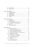
...6 Box Contents ...6 GA-P35-DQ6 Motherboard Layout 7 Block Diagram ...8 Chapter 1 Hardware Installation 9 1-1 Installation Precautions 9 1-2 Product Specifications 10 1-3 Installing the CPU and CPU Cooler 13 1-3-1 Installing the CPU 13 1-3-2 Installing the CPU Cooler 15 1-3-3 Removing - Gigabyte GA-P35-DQ6 | Manual - Page 5
with the @BIOS Utility 71 4-3 EasyTune 5 ...73 4-4 Windows Vista ReadyBoost 74 Chapter 5 Appendix ...75 5-1 Configuring SATA Hard Drive(s 75 5-1-1 Configuring Intel® ICH9R SATA Controllers 75 5-1-2 Configuring GIGABYTE SATA2 SATA Controller 81 5-1-3 Making a SATA RAID/AHCI Driver Diskette 87 - Gigabyte GA-P35-DQ6 | Manual - Page 6
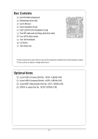
Box Contents GA-P35-DQ6 motherboard Motherboard driver disk User's Manual Quick Installation Guide Intel® LGA775 CPU Installation Guide One IDE cable and one floppy disk drive cable Four SATA 3Gb/s cables Two SATA brackets I/O Shield Two screw nuts The box contents above are - Gigabyte GA-P35-DQ6 | Manual - Page 7
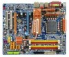
GA-P35-DQ6 Motherboard Layout KB_MS COAXIAL OPTICAL SYS_FAN1 ATX_12V_2X LGA775 PWR_FAN PCIE_12V ATX COMA LPT USB 1394 GA-P35-DQ6 USB LAN F_AUDIO CPU_FAN AUDIO PCIE_1 Intel® P35 F_USB3 F_USB2 F_USB1 Intel® ICH9R SATAII4 SATAII5 SATAII0 SATAII1 SATAII2 SATAII3 GIGABYTE SATA2 IDE - Gigabyte GA-P35-DQ6 | Manual - Page 8
/66/ 33 IDE Channel GIGABYTE SATA2 PCI Bus TSB43AB23 3 IEEE 1394a LGA775 Processor CPU CLK+/- (333/266/200 MHz) Host Interface DDR2 1066/800/667 MHz Intel® P35 Dual Channel Memory MCH CLK (333/266/200 MHz) Intel® ICH9R CODEC Dual BIOS 6 SATA 3Gb/s 12 USB Ports IT8718 Floppy LPT Port - Gigabyte GA-P35-DQ6 | Manual - Page 9
manual and follow these procedures: • Prior to installation, do not remove or break motherboard as a motherboard, CPU or memory. If power supply cable from the motherboard, make sure the power supply has been turned off. • Before turning on the power, make sure the power supply voltage has been set - Gigabyte GA-P35-DQ6 | Manual - Page 10
in the LGA 775 package (Go to GIGABYTE's website for the latest CPU support list.) Š Support for Intel® Hyper-Threading Technology Š L2 cache varies with CPU Š 1333/1066/800 MHz FSB Š North Bridge: Intel® P35 Chipset Š South Bridge: Intel® ICH9R Š 4 x 1.8V DDR2 DIMM sockets supporting up to - Gigabyte GA-P35-DQ6 | Manual - Page 11
Monitor Š System voltage detection Š CPU/System temperature detection Š CPU/System/Power fan speed detection Š CPU overheating warning Š CPU/System/Power fan fail warning Š CPU fan speed control BIOS Š 2 x 8 Mbit flash Š Use of licensed AWARD BIOS Š Support for Dual BIOSTM Š PnP 1.0a - Gigabyte GA-P35-DQ6 | Manual - Page 12
unavailable. (Note 3) Available functions in Easytune may differ by motherboard model. (Note 4) The adjustable CPU voltage range depends on the CPU being used. (Note 5) Due to chipset limitation, Intel ICH9R RAID driver does not support Windows 2000 operating system. GA-P35-DQ6 Motherboard - 12 - - Gigabyte GA-P35-DQ6 | Manual - Page 13
enabled (Refer to Chapter 2, "BIOS Setup," "Advanced BIOS Features," for instructions on enabling the HT Technology.) 1-3-1 Installing the CPU A. Locate the alignment keys on the motherboard CPU socket and the notches on the CPU. LGA775 CPU Socket Alignment Key LGA 775 CPU Alignment Key Pin One - Gigabyte GA-P35-DQ6 | Manual - Page 14
pin one corner of the CPU socket (or you may align the CPU notches with the socket alignment keys) and gently insert the CPU into position. Step 5: Once the CPU is properly inserted, replace the load plate and push the CPU socket lever back into its locked position. GA-P35-DQ6 Motherboard - 14 - - Gigabyte GA-P35-DQ6 | Manual - Page 15
installation manual for instructions on installing the cooler.) Step 5: After the installation, check the back of the motherboard. If the push pin is inserted as the picture above, the installation is complete. Step 6: Finally, attach the power connector of the CPU cooler to the CPU fan header - Gigabyte GA-P35-DQ6 | Manual - Page 16
and complete the steps to remove the Crazy Cool heatsink. (Remember to replace the copper fin.) Refer to your CPU cooler installation manual for instructions on installing the cooler. (Note) The components received may vary in appearance from the products illustrated. GA-P35-DQ6 Motherboard - 16 - - Gigabyte GA-P35-DQ6 | Manual - Page 17
Make sure that the motherboard supports the memory. It is recommended that memory of the same capacity, brand, speed, and chips be used. (Go to GIGABYTE's website for the latest memory support list.) • Always turn off the computer and unplug the power cord from the power outlet before installing the - Gigabyte GA-P35-DQ6 | Manual - Page 18
in the picture on the left, place your fingers on the top edge of the memory, push down on the memory and insert it vertically into the memory socket. Step 2: The clips at both ends of the socket will snap into place when the memory module is securely inserted. GA-P35-DQ6 Motherboard - 18 - - Gigabyte GA-P35-DQ6 | Manual - Page 19
motherboard supports the expansion card. Carefully read the manual that came with your expansion card. • Always turn off the computer and unplug the power cord from the power , go to BIOS Setup to make any required BIOS changes for your expansion card(s). 7. Install the driver provided with the - Gigabyte GA-P35-DQ6 | Manual - Page 20
pull the card straight up from the slot. • The motherboard provides a PCIE_12V power connector, which can supply extra power to the onboard PCI Express x16 slots. When you install two graphics cards, connect the power cable from your power supply to this connector. GA-P35-DQ6 Motherboard - 20 - - Gigabyte GA-P35-DQ6 | Manual - Page 21
to the SATA port on your motherboard. Step 3: Step 4: Connect the power Plug one end of the cable from the SATA signal cable into bracket to the power the external SATA supply. connector on the bracket. Then attach the SATA power cable to the power connec- Step 5: tor on the bracket - Gigabyte GA-P35-DQ6 | Manual - Page 22
to a back panel connector, first remove the cable from your device and then remove it from the motherboard. • When removing the cable, pull it straight out from the connector. Do not rock it side to side to prevent an electrical short inside the cable connector. GA-P35-DQ6 Motherboard - 22 - - Gigabyte GA-P35-DQ6 | Manual - Page 23
to perform different functions via the audio software. Only microphones still MUST be connected to the default Mic in jack ( ). Refer to the instructions on setting up a 2/4/5.1/ 7.1-channel audio configuration in Chapter 5, "Configuring 2/4/5.1/7.1-Channel Audio." - 23 - Hardware Installation - Gigabyte GA-P35-DQ6 | Manual - Page 24
the devices and your computer. Unplug the power cord from the power outlet to prevent damage to the devices. • After installing the device and before turning on the computer, make sure the device cable has been securely attached to the connector on the motherboard. GA-P35-DQ6 Motherboard - 24 - - Gigabyte GA-P35-DQ6 | Manual - Page 25
orientation. The 12V power connector mainly supplies power to the CPU. If the 12V power connector is not connected, the computer will not start. • Use of a power supply providing a 2x4 12V power connector is recommended by the CPU manufacturer when using an Intel Extreme Edition CPU (130W). • To - Gigabyte GA-P35-DQ6 | Manual - Page 26
This power connector can supply extra power to the PCI Express x16 slots on the motherboard. Connect the power supply cable to this connector when using two graphics cards. Failure to do so may lead to an unstable system. 1 PIin No. Definition 1 NC 2 GND 3 GND 4 +12V GA-P35-DQ6 Motherboard - Gigabyte GA-P35-DQ6 | Manual - Page 27
it in the correct orientation. Most fans are designed with color-coded power connector wires. A red power connector wire indicates a positive connection and requires a +12V voltage. The black connector wire is the ground wire. The motherboard supports CPU fan speed control, which requires the use of - Gigabyte GA-P35-DQ6 | Manual - Page 28
IDE connector supports up to two set the jumpers and the cabling according to the role of the IDE devices (for example, master or slave). (For information about configuring master/slave settings for the IDE devices, read the instructions from the device manufacturers.) 1 2 GA-P35-DQ6 Motherboard - Gigabyte GA-P35-DQ6 | Manual - Page 29
SATA 1.5Gb/s standard. Each SATA connector supports a single SATA device. The GIGABYTE SATA2 controller supports RAID 0 and RAID 1. Refer to Chapter 5, "Configuring SATA Hard Drive(s)," for instructions on configuring a RAID array. 1 7 7 1 GSATAII0 GSATAII1 Pin No. 1 2 3 4 5 6 7 Definition - Gigabyte GA-P35-DQ6 | Manual - Page 30
- 3 MPD- System Status LED S0 On S1 Blinking S3/S4/S5 Off 13) BATTERY The battery provides power to keep the values (such as BIOS configurations, date, and time information) in the CMOS when must be handled in accordance with local environmental regulations. GA-P35-DQ6 Motherboard - 30 - - Gigabyte GA-P35-DQ6 | Manual - Page 31
status by issuing a beep code. One single short beep will be heard if no problem is detected at system startup. If a problem is detected, the BIOS may issue beeps in different patterns to indicate the problem. Refer to Chapter 5, "Troubleshooting," for information about beep codes. • HD (IDE Hard - Gigabyte GA-P35-DQ6 | Manual - Page 32
10 NC • The front panel audio header supports HD audio by default. If your chassis provides an AC'97 front panel audio module, refer to the instructions on how to activate AC'97 functioninality via header. 1 Pin No. Definition 1 CD-L 2 GND 3 GND 4 CD-R GA-P35-DQ6 Motherboard - 32 - - Gigabyte GA-P35-DQ6 | Manual - Page 33
connect to an audio device that supports digital audio out via an optional S/PDIF in cable. For purchasing the optional S/PDIF in cable, please contact the local dealer. Pin No. Definition 1 1 Power 2 SPDIFI 3 GND 18) F_USB1/F_USB2/F_USB3/F_USB4 (USB Headers, Yellow) The headers conform to - Gigabyte GA-P35-DQ6 | Manual - Page 34
9 1 TPA+ 2 TPA- 3 GND 4 GND 5 TPB+ 6 TPB- 7 Power (12V) 8 Power (12V) 9 No Pin 10 GND • Do not plug the USB bracket cable into the IEEE 1394a header. • Prior to installing the IEEE 1394a bracket, LAD0 GND RSVO RSV1 SB3V SERIRQ GND CLKRUN LPCPD RSV2 GA-P35-DQ6 Motherboard - 34 - - Gigabyte GA-P35-DQ6 | Manual - Page 35
turn off your computer and unplug the power cord from the power outlet before clearing the CMOS values. • motherboard. • After system restart, go to BIOS Setup to load factory defaults (select Load Optimized Defaults) or manually configure the BIOS settings (refer to Chapter 2, "BIOS Setup," for BIOS - Gigabyte GA-P35-DQ6 | Manual - Page 36
English GA-P35-DQ6 Motherboard - 36 - - Gigabyte GA-P35-DQ6 | Manual - Page 37
that searches and downloads the latest version of BIOS from the Internet and updates the BIOS. For instructions on using the Q-Flash and @BIOS utilities, refer to Chapter 4, "BIOS Update Utilities." • Because BIOS flashing is potentially risky, if you do not encounter problems using the current - Gigabyte GA-P35-DQ6 | Manual - Page 38
, the device boot order will still be based on BIOS Setup settings. You can access Boot Menu again to change the first boot device setting as needed. Q-Flash Press the key to access the Q-Flash utility directly without having to enter BIOS Setup first. GA-P35-DQ6 Motherboard - 38 - - Gigabyte GA-P35-DQ6 | Manual - Page 39
Software ` Standard CMOS Features ` Advanced BIOS Features ` Integrated Peripherals ` Power Management Setup ` PnP/PCI Configurations ` PC Health Status ` MB Intelligent Tweaker(M.I.T.) Load Fail-Safe Defaults Load Optimized Defaults Set Supervisor Password Set User Password Save & Exit Setup Exit - Gigabyte GA-P35-DQ6 | Manual - Page 40
CMOS and exit BIOS Setup. (Pressing can also carry out this task.) „ Exit Without Saving Abandon all changes and the previous settings remain in effect. Pressing to the confirmation message will exit BIOS Setup. (Pressing can also carry out this task.) GA-P35-DQ6 Motherboard - 40 - - Gigabyte GA-P35-DQ6 | Manual - Page 41
Support Memory CMOS Setup Utility-Copyright (C) 1984-2007 Award Software Standard CMOS Features 640K 511M 512M Item Help Menu Level` KLJI: Move Enter: Select F5: Previous Values +/-/PU/PD: Value F10: Save F6: Fail-Safe Default ESC: Exit F1: General Help F7: Optimized Defaults Date Sets - Gigabyte GA-P35-DQ6 | Manual - Page 42
and are determined by the BIOS POST. Base Memory Also called conventional memory. Typically, 640 KB will be reserved for the MS-DOS operating system. Extended Memory The amount of extended memory. Total Memory The total amount of memory installed on the system. GA-P35-DQ6 Motherboard - 42 - - Gigabyte GA-P35-DQ6 | Manual - Page 43
BIOS Features ` Hard Disk Boot Priority First Boot Device Second Boot Device Third Boot Device Password Check HDD S.M.A.R.T. Capability CPU Hyper-Threading (Note) Limit CPUID Max. to 3 (Note) No-Execute Memory Protect (Note) CPU Enhanced Halt (C1E) (Note) CPU Thermal Monitor 2(TM2) (Note) CPU - Gigabyte GA-P35-DQ6 | Manual - Page 44
GIGABYTE Logo Sets PCI Express graphics card on the second PCIe x16 slot (PCIE_16_2) as the first display. (Note) This item is present only if you install a CPU that supports this feature. For more information about Intel CPUs' unique features, please visit Intel's website. GA-P35-DQ6 Motherboard - Gigabyte GA-P35-DQ6 | Manual - Page 45
-2007 Award Software Integrated Peripherals SATA RAID/AHCI Mode SATA Port0-3 Native Mode USB Controller USB 2.0 Controller USB Keyboard Support USB Mouse Support Legacy USB storage detect Azalia Codec Onboard H/W 1394 Onboard H/W LAN ` SMART LAN Onboard LAN Boot ROM Onboard SATA/IDE Device Onboard - Gigabyte GA-P35-DQ6 | Manual - Page 46
party add-in network card instead of using the onboard LAN, set this item to Disabled. SMART LAN (LAN Cable Diagnostic Function) the figure above. When LAN Cable Is Functioning Normally... If no cable problem is detected on the LAN cable connected to a Gigabit hub or a GA-P35-DQ6 Motherboard - 46 - - Gigabyte GA-P35-DQ6 | Manual - Page 47
(AHCI) is an interface specification that allows the storage driver to enable advanced Serial ATA features such as Native Command Queuing and RAID/IDE hot plug. For more information about AHCI, please visit Intel's website. Enables RAID for the SATA controller. (The IDE controller still operates - Gigabyte GA-P35-DQ6 | Manual - Page 48
least 1A on the 5VSB lead. (Default: Enabled) Power On by Ring Allows the system to be awakened from an ACPI sleep state by a wake-up signal from a modem that supports wake-up function. (Default: Enabled) (Note) Supported on Windows® Vista® operating system only. GA-P35-DQ6 Motherboard - 48 - - Gigabyte GA-P35-DQ6 | Manual - Page 49
PS/2 keyboard wake-up event. Note: you need an ATX power supply providing at least 1A on the 5VSB lead. Disabled Disables this function. (Default) Password Set a password with 1~5 characters to turn on the system. Keyboard 98 Press POWER button on the Windows 98 keyboard to turn on the system - Gigabyte GA-P35-DQ6 | Manual - Page 50
Help F7: Optimized Defaults BIOS auto-assigns IRQ to the first PCI slot. (Default) Assigns IRQ 3,4,5,7,9,10,11,12,14,15 to the first PCI slot. BIOS auto-assigns IRQ to the second PCI slot. (Default) Assigns IRQ 3,4,5,7,9,10,11,12,14,15 to the second PCI slot. GA-P35-DQ6 Motherboard - 50 - - Gigabyte GA-P35-DQ6 | Manual - Page 51
voltages. Current CPU/System Temperature Displays current CPU/system temperature. Current CPU/SYSTEM/POWER FAN Speed (RPM) Displays current CPU/system/power fan speed. CPU Warning Temperature Sets the warning threshold for CPU temperature. When CPU temperature exceeds the threshold, BIOS will emit - Gigabyte GA-P35-DQ6 | Manual - Page 52
, selecting PWM mode may not effectively reduce the fan speed. (Note) Before setting this item to Intel(R) QST, make sure at least DDRII1 or DDRII2 socket in Channel 0 is populated. A small portion of system memory will be shared when Intel® QST is enabled. GA-P35-DQ6 Motherboard - 52 - - Gigabyte GA-P35-DQ6 | Manual - Page 53
Robust Graphics Booster (R.G.B.) helps to enhance the performance of the graphics chip and memory. Auto allows the BIOS to automatically set the R.G.B. mode based on system configurations. Options are: Auto (default), Fast, Turbo. CPU Clock Ratio (Note) Allows you to alter the clock ratio for the - Gigabyte GA-P35-DQ6 | Manual - Page 54
different memory timing configurations. If your system becomes unstable after you overclock the DDR2 memory, select Option 1 or Option 2 to help make your system more stable. Option 1 Memory Timing Configuration 1. (Default) Option 2 Memory Timing Configuration 2. GA-P35-DQ6 Motherboard - 54 - Gigabyte GA-P35-DQ6 | Manual - Page 55
whether to manually set the system voltages. Auto lets BIOS automatically set the system voltages as required. Manual allows all voltage control items below to be configurable. (Default: Manual) DDR2 OverVoltage Control Allows you to to set memory voltage. Normal Supplies the memory voltage as - Gigabyte GA-P35-DQ6 | Manual - Page 56
Press on this item and then press the key to load the optimal BIOS default settings. The BIOS defaults settings helps the system to operate in optimum state. Always load the Optimized defaults after updating the BIOS or after clearing the CMOS values. GA-P35-DQ6 Motherboard - 56 - - Gigabyte GA-P35-DQ6 | Manual - Page 57
the supervisor password (or user password) at system startup to continue system boot. In BIOS Setup, you must enter the supervisor password if you wish to make changes to BIOS settings. The user password only allows you to view the BIOS settings but not to make changes. To clear the password, press - Gigabyte GA-P35-DQ6 | Manual - Page 58
` Advanced BIOS Features Load Optimized Defaults ` Integrated Peripherals Set Supervisor Password ` Power Management Setup exits the BIOS Setup without saving the changes made in BIOS Setup to the CMOS. Press or to return to the BIOS Setup Main Menu. GA-P35-DQ6 Motherboard - 58 - Gigabyte GA-P35-DQ6 | Manual - Page 59
other drivers. • After the drivers are installed, follow the onscreen instructions to restart your system. You can install other applications included in the motherboard driver disk. • For USB 2.0 driver support under the Windows XP operating system, please install the Windows XP Service Pack - Gigabyte GA-P35-DQ6 | Manual - Page 60
all the tools and applications that GIGABYTE develops and some free software. You may press the Install button following an item to install it. 3-3 Driver CD Information This page provides information about the drivers, applications and tools in this driver disk. GA-P35-DQ6 Motherboard - 60 - - Gigabyte GA-P35-DQ6 | Manual - Page 61
English 3-4 Hardware Information This page provides information about the hardware devices on this motherboard. 3-5 Contact Us Check the contacts information of the GIGABYTE headquarter in Taiwan and the overseas branch offices on the last page of this manual. - 61 - Drivers Installation - Gigabyte GA-P35-DQ6 | Manual - Page 62
English GA-P35-DQ6 Motherboard - 62 - - Gigabyte GA-P35-DQ6 | Manual - Page 63
your system soon after the operating system and drivers are installed. • The amount of data and restore it. System Requirements: • Intel® x86 platform • At least 64 MB of system memory • VESA compatible graphics card USB hard drives are not supported. • Hard drives in RAID/AHCI mode are not supported - Gigabyte GA-P35-DQ6 | Manual - Page 64
Installing Windows XP and Partitioning the Hard Drive 1. Set CD-ROM drive as the first boot device under "Advanced BIOS Features" in the BIOS Setup program. Save the changes and exit. , NTFS) and begin the installation of the operating system (Figure 3). Figure 3 GA-P35-DQ6 Motherboard - 64 - - Gigabyte GA-P35-DQ6 | Manual - Page 65
Figure 4 Figure 5 5. If your hard drive is not properly partitioned before you install the operating system, you may create new partitions using free space on your hard drive (Figure 6, 7). However, if Disk Management shows the hard drive only contains the System partition without any unallocated - Gigabyte GA-P35-DQ6 | Manual - Page 66
Software, Inc. Intel P35 BIOS for P35-DQ6 F1e . . . . : BIOS Setup : XpressRecovery2 : Boot Menu : Qflash 03/28/2007-P35-ICH9-6A790G0EC- Disk Management to check disk allocation. Figure 12 GA-P35-DQ6 Motherboard Xpress Recovery2 will automatically create a new partition to store the - Gigabyte GA-P35-DQ6 | Manual - Page 67
English D. Using the Restore Function in Xpress Recovery2 Select RESTORE to restore the backup to your hard drive in case the system breaks down. The RESTORE option will not be present if no backup is created before (Figure 13, 14). Figure 13 Figure 14 E. Removing the Backup 1. If you wish to - Gigabyte GA-P35-DQ6 | Manual - Page 68
. Intel P35 BIOS for P35-DQ6 F1e . . . . : BIOS Setup : XpressRecovery2 : Boot Menu : Qflash 03/28/2007-P35-ICH9-6A790G0EC-00 Because BIOS flashing is potentially risky, please do it with caution. Inadequate BIOS flashing may result in system malfunction. GA-P35-DQ6 Motherboard - Gigabyte GA-P35-DQ6 | Manual - Page 69
Sa0vefilBeI(Os)SfotounDdrive EnteFr l:oRppuyn A KL:Move ESC:Reset :Power Off HDD 0-0 Total size : 0 Free size : 0 3. Select the BIOS update file and press . Make sure the BIOS update file matches your motherboard model. Step 2: The process of the system reading the - Gigabyte GA-P35-DQ6 | Manual - Page 70
Setup F11: Save CMOS to BIOS F12: Load CMOS from BIOS Load Optimized Defaults Press to load BIOS defaults Step 6: Select Save & Exit Setup and then press to save settings to CMOS and exit BIOS Setup. The procedure is complete after the system restarts. GA-P35-DQ6 Motherboard - 70 - - Gigabyte GA-P35-DQ6 | Manual - Page 71
and Using @BIOS: Use the motherboard driver disk included with the motherboard to install @BIOS. • Installing the @BIOS utility. • Accessing the @BIOS utility. Select @BIOS and click Install. Click Start>Program>Gigabyte>BIOS>@BIOS C. Options and Instructions: 1. Save the Current BIOS File In - Gigabyte GA-P35-DQ6 | Manual - Page 72
in an unbootable system. • If the BIOS update file for your motherboard is not present on the @BIOS server site, please manually download the BIOS update file from GIGABYTE's website and follow the instructions in "Update the BIOS without Using the Internet Update Function" below. Step 4: As the - Gigabyte GA-P35-DQ6 | Manual - Page 73
the BIOS Setup program. EasyTune 5 provides the following functions (Note 1): overclocking/overvoltage, C.I.A./ M.I.B. (Note 2), smart fan control, and hardware monitoring and warning. (For instructions on using EasyTune5, read or download the information on/from the Support\Motherboard\Utility - Gigabyte GA-P35-DQ6 | Manual - Page 74
speed. Click Apply and then OK to activate ReadyBoost function. • The USB flash drive has to have above 256 MB of memory capacity. • The recommend amount of memory to use for ReadyBoost acceleration is one to three times the amount of RAM installed in your computer. GA-P35-DQ6 Motherboard - 74 - - Gigabyte GA-P35-DQ6 | Manual - Page 75
from your power supply to the hard drive. (Note 1) Skip this step if you do not want to create RAID array on the SATA controller. (Note 2) Required when the SATA controller is set to AHCI or RAID mode. (Note 3) Due to chipset limitation, Intel ICH9R RAID driver does not support Windows 2000 - Gigabyte GA-P35-DQ6 | Manual - Page 76
Defaults Step 2: Save changes and exit BIOS Setup. The BIOS Setup menus described in this section may differ from the exact settings for your motherboard. The actual BIOS Setup menu options you will see shall depend on the motherboard you have and the BIOS version. GA-P35-DQ6 Motherboard - 76 - - Gigabyte GA-P35-DQ6 | Manual - Page 77
C. Configuring a RAID array in RAID BIOS Enter the RAID BIOS setup utility to configure a RAID array. Skip this step and proceed to the installation of Windows operating system for a non-RAID configuration. Step 1: After the POST memory test begins and before the operating system boot begins, look - Gigabyte GA-P35-DQ6 | Manual - Page 78
: RAID Level : Disks : Strip Size : Capacity : Volume0 RAID0(Stripe) Select Disks 128KB 223.6 GB Create Volume [ HELP ] The following are typical values: RAID0 - 128KB RAID10 - 64KB RAID5 - 64KB [K L ]-Change [TAB]-Next [ESC]-Previous Menu Figure 5 [ENTER]-Select GA-P35-DQ6 Motherboard - 78 - Gigabyte GA-P35-DQ6 | Manual - Page 79
Disk(0) [KL]-Select [ESC]-Exit Figure 7 [ENTER]-Select Menu To exit the ICH9R RAID BIOS utility, press or select Exit in MAIN MENU. Now, you may proceed to create the SATA RAID/AHCI driver diskette and the installation of the SATA RAID/ACHI driver and operating system. - 79 - Appendix - Gigabyte GA-P35-DQ6 | Manual - Page 80
. Name Volume0 Intel(R) Matrix Storage Manager option ROM v7.5.0.1014 ICH9R wRAID5 Copyright(C) 2003-07 Intel Corporation. All Rights the disks to non-RAID. WARNING: ALL DISK DATA WILL BE DELETED. [K L ]-Select [ESC]-Previous Menu Figure 8 [DEL]-Delete Volume GA-P35-DQ6 Motherboard - 80 - - Gigabyte GA-P35-DQ6 | Manual - Page 81
for the SATA port. (For example, on this motherboard, the GSATAII0 and GSATAII1 ports are supported by GIGABYTE SATA2.) Then connect the power connector from your power supply to the hard drive. B. Configuring SATA controller mode and device boot order in BIOS Setup Make sure to configure the SATA - Gigabyte GA-P35-DQ6 | Manual - Page 82
-RAID [ RAID Disk Drive List ] [IJTAB]-Switch Window [KL]-Select ITEM [ENTER]-Action Figure 3 [ESC]-Exit Note: In the main screen, you can select a hard drive in the Hard Disk Drive List block and press to see detailed information about the selected hard drive. GA-P35-DQ6 Motherboard - Gigabyte GA-P35-DQ6 | Manual - Page 83
the main screen, press on the Create RAID Disk Drive item. Then the Create New RAID screen appears (Figure 4). GIGABYTE Technology Corp. PCIE-to-SATAII/IDE RAID Controller BBIOSv1.06.59 [ Create New RAID ] [ Hard Disk Drive List ] Name: Level: Disks: Block: Size: GRAID_ 0-Stripe Select - Gigabyte GA-P35-DQ6 | Manual - Page 84
/Status Non-RAID Non-RAID Confirm Creation [ RAID Disk Drive List ] Create RAID [onHethlpe ]select HDD(Y/N)?Y CONFIRM RAID CREATION ALL DATA ON THE SELECTED HARD DISK WILL BE LOST WHEN EXIT WITH SAVING [KL]-Switch Unit [DEL,BS]-Delete Number Figure 7 [ENTER]-Next GA-P35-DQ6 Motherboard - 84 - Gigabyte GA-P35-DQ6 | Manual - Page 85
array will be displayed in the RAID Disk Drive List block (Figure 8). GIGABYTE Technology Corp. PCIE-to-SATAII/IDE RAID Controller BIOSv1.06.59 [ Main Menu ] [ Hard Disk Drive List ] Create RAID Disk Drive Delete RAID Disk Drive Revert HDD to Non-RAID Solve Mirror Conflict Rebuild Mirror Drive - Gigabyte GA-P35-DQ6 | Manual - Page 86
120 GB Type/Status RAID Inside RAID Inside [ RAID Disk Drive List ] Model Name ` RDD0: GRAID ALL DATA ON THE RAID WILL LOST!! ARE YOU SURE TO DELETE (Y/N)? N RAID Level Capacity Status 0-Stripe 240 GB Normal Members(HDDx) 01 [KL]-Select RAID GA-P35-DQ6 Motherboard [SPACE]-Mark Delete [DEL - Gigabyte GA-P35-DQ6 | Manual - Page 87
to a floppy disk. See the instructions below about how to copy the driver in MS-DOS mode(Note). Prepare a startup disk that has CD-ROM support and a blank formatted floppy disk. Step 1: Insert the prepared startup disk and motherboard driver disk in your system. Boot from the startup disk. Once at - Gigabyte GA-P35-DQ6 | Manual - Page 88
manufacturer, press S. * If you do not have any device support disks from a mass storage device manufacturer, or do not want to specify additional mass storage devices for use with Windows, press ENTER. S=Specify Additional Device ENTER=Continue F3=Exit Figure 2 GA-P35-DQ6 Motherboard - 88 - - Gigabyte GA-P35-DQ6 | Manual - Page 89
the Intel ICH9R SATA RAID/AHCI driver in the floppy disk, a controller menu similar to Figure 3 below will appear. Use the arrow keys to select one of the items displayed and press . If you set the SATA RAID/AHCI Mode item in BIOS Setup to RAID mode, select Intel(R) ICH9 SATA RAID Controller - Gigabyte GA-P35-DQ6 | Manual - Page 90
manufacturer, press S. * If you do not have any device support disks from a mass storage device manufacturer, or do not want to specify additional mass storage devices for use with Windows, press ENTER. S=Specify Additional Device ENTER=Continue F3=Exit Figure 6 GA-P35-DQ6 Motherboard - 90 - - Gigabyte GA-P35-DQ6 | Manual - Page 91
English Step 4: After the SATA controller driver installation is completed, you can proceed with the Windows XP installation. WindowsXP Professional Setup Welcome to Setup. This port of the Setup program prepares Microsoft(R) Windows (R) XP to run on your computer. To set up Windows XP now, press - Gigabyte GA-P35-DQ6 | Manual - Page 92
microphone to the Mic in or Line in jack and manually configure the jack for microphone functionality. • If your front panel audio supports Intel HD Audio standard, you can have both the front out, Rear speaker out, Center/Subwoofer speaker out, and Side speaker out. GA-P35-DQ6 Motherboard - 92 - - Gigabyte GA-P35-DQ6 | Manual - Page 93
English Step 2: Click the Audio I/O tab. In the speaker list on the left, select 2CH Speaker, 4CH Speaker, 6CH Speaker, or 8CH Speaker according to the type of speaker configuration you wish to set up. Step 3: Everytime you connect an audio device to an audio jack, the Connected device box appears. - Gigabyte GA-P35-DQ6 | Manual - Page 94
for audio processing. A. Installing the S/PDIF In Cable: Step 1: First, attach the connector at the end of the cable to the SPDIF_IN header on your motherboard. Step 2: Secure the metal bracket to the chassis back panel with a screw. GA-P35-DQ6 Motherboard - 94 - - Gigabyte GA-P35-DQ6 | Manual - Page 95
signals. S/PDIF Coaxial Cable S/PDIF Optical Cable C. Configuring S/PDIF out: Click the tool icon in the DIGITAL section. In the S/PDIF In/Out Settings dialog box, select an output sampling rate and select (or disable) the output source. Click OK to complete the configuration. - 95 - Appendix - Gigabyte GA-P35-DQ6 | Manual - Page 96
virtual surround sound environment(Note). After installing the audio driver, at the center bottom of the Audio Control Panel the Audio Control Panel. Either click DTS Interactive in the upper left list or click the dts INTERAC- TIVE button at the center bottom of . GA-P35-DQ6 Motherboard - 96 - - Gigabyte GA-P35-DQ6 | Manual - Page 97
Control Panel, click the Audio I/O tab. In the upper left list, click Digital PCM Output. Enable this function to allow digital the S/PDIF OUT. 5-2-3 Configuring Microphone Recording Step 1: After installing the audio driver, the Audio Manager icon will appear in your system tray. Double-click the - Gigabyte GA-P35-DQ6 | Manual - Page 98
that you set the volume list, select Realtek HD Audio Input. Then set the recording sound level properly. Do NOT mute the recording sound, or you will not hear any sound when playing back the recording you just made. Select Realtek HD Audio Input in the Mixer devie list GA-P35-DQ6 Motherboard - Gigabyte GA-P35-DQ6 | Manual - Page 99
Step 6: To raise the recording and playing sound for the microphone, go to Options in Master Volume and select Advanced Controls. Click the Advanced button under a volume control option (e.g. Front Green In, Front Pink In). In the Other Controls field, select the 1 Microphone Boost check box. Step - Gigabyte GA-P35-DQ6 | Manual - Page 100
: CMOS setting error 1 long, 1 short: Memory or motherboard error 1 long, 2 short: Monitor or graphics card error 1 long, 3 short: Keyboard error 1 long, 9 short: BIOS ROM error Continuous long beeps: Graphics card not inserted properly Continuous short beeps: Power error GA-P35-DQ6 Motherboard - Gigabyte GA-P35-DQ6 | Manual - Page 101
any troubles during system startup, follow the troubleshooting procedure below to solve the problem. START Turn off the power. Remove all peripherals, connecting cables, and power cord etc. Make sure the motherboard does not short-circuit with the chassis or other metal objects. No Check if the CPU - Gigabyte GA-P35-DQ6 | Manual - Page 102
and solved. END If the procedure above is unable to solve your problem, contact the place of purchase or local dealer for help. Or go to the Support\Technical Service Zone page to submit your question. Our customer service staff will reply you as soon as possible. GA-P35-DQ6 Motherboard - 102 - - Gigabyte GA-P35-DQ6 | Manual - Page 103
- 103 - Appendix English - Gigabyte GA-P35-DQ6 | Manual - Page 104
English GA-P35-DQ6 Motherboard - 104 - - Gigabyte GA-P35-DQ6 | Manual - Page 105
- 105 - Appendix English - Gigabyte GA-P35-DQ6 | Manual - Page 106
English GA-P35-DQ6 Motherboard - 106 - - Gigabyte GA-P35-DQ6 | Manual - Page 107
- 107 - Appendix English - Gigabyte GA-P35-DQ6 | Manual - Page 108
English GA-P35-DQ6 Motherboard - 108 - - Gigabyte GA-P35-DQ6 | Manual - Page 109
- 109 - Appendix English - Gigabyte GA-P35-DQ6 | Manual - Page 110
TEL: +86-24-83992901 FAX: +86-24-83992909 India GIGABYTE TECHNOLOGY (INDIA) LIMITED WEB address : http://www.giga-byte.co.in/ Saudi Arabia WEB address : http://www.gigabyte.com.sa Australia GIGABYTE TECHNOLOGY PTY. LTD. WEB address : http://www.gigabyte.com.au GA-P35-DQ6 Motherboard - 110 - - Gigabyte GA-P35-DQ6 | Manual - Page 111
.co.yu You may go to the GIGABYTE website, select your language in the language list on the top right corner of the website. GIGABYTE Global Service System To submit a technical or non-technical (Sales/ Marketing) question, please link to : http://ggts.gigabyte.com.tw Then select your language to - Gigabyte GA-P35-DQ6 | Manual - Page 112
- 112 -
-
 1
1 -
 2
2 -
 3
3 -
 4
4 -
 5
5 -
 6
6 -
 7
7 -
8
-
9
-
10
-
11
-
12
-
13
-
14
-
15
-
16
-
17
-
18
-
19
-
20
-
21
-
22
-
23
-
24
-
25
-
26
-
27
-
28
-
29
-
30
-
31
-
32
-
33
-
34
-
35
-
36
-
37
-
38
-
39
-
40
-
41
-
42
-
43
-
44
-
45
-
46
-
47
-
48
-
49
-
50
-
51
-
52
-
53
-
54
-
55
-
56
-
57
-
58
-
59
-
60
-
61
-
62
-
63
-
64
-
65
-
66
-
67
-
68
-
69
-
70
-
71
-
72
-
73
-
74
-
75
-
76
-
77
-
78
-
79
-
80
-
81
-
82
-
83
-
84
-
85
-
86
-
87
-
88
-
89
-
90
-
91
-
92
-
93
-
94
-
95
-
96
-
97
-
98
-
99
-
100
-
101
-
102
-
103
-
104
-
105
-
106
-
107
-
108
-
109
-
110
-
111
-
112
 |
 |

GA-P35-DQ6
LGA775 socket motherboard for Intel
®
Core
TM
processor family/
Intel
®
Pentium
®
processor family/Intel
®
Celeron
®
processor family
User's Manual
Rev. 1002
12ME-P35DQ6-1002R
*
The WEEE marking on the product indicates this product must not be disposed of with user's other household waste
and must be handed over to a designated collection point for the recycling of waste electrical and electronic equipment!!
*
The WEEE marking applies only in European Union's member states.