Gigabyte GA-VM800PMC Manual
Gigabyte GA-VM800PMC Manual
 |
View all Gigabyte GA-VM800PMC manuals
Add to My Manuals
Save this manual to your list of manuals |
Gigabyte GA-VM800PMC manual content summary:
- Gigabyte GA-VM800PMC | Manual - Page 1
GA-VM800PMC Intel® CoreTM 2 Duo / Intel® Pentium® D / Pentium® 4 / Celeron® D LGA775 Processor Motherboard User's Manual Rev. 1003 12ME-VM800PMC-1003R * The WEEE marking on the product indicates this product must not be disposed of with user's other household waste and must be handed over - Gigabyte GA-VM800PMC | Manual - Page 2
Motherboard GA-VM800PMC Dec. 5, 2006 Motherboard GA-VM800PMC Dec. 5, 2006 - Gigabyte GA-VM800PMC | Manual - Page 3
product information and specifications, please carefully read the "Product User Manual". „ For detailed information related to Gigabyte's unique features, please go to "Technology Guide" section on Gigabyte's website to read or download the information you need. For more product details, please - Gigabyte GA-VM800PMC | Manual - Page 4
OptionalAccessories ...6 GA-VM800PMC Motherboard Layout 7 Block Diagram ...8 Chapter 1 Hardware Installation 9 1-1 Considerations Prior to Installation 9 1-2 Feature Summary 10 1-3 Installation of the CPU and CPU Cooler 12 1-3-1 Installation of the CPU 12 1-3-2 Installation of the CPU Cooler - Gigabyte GA-VM800PMC | Manual - Page 5
47 Chapter 4 Appendix 49 4-1 Unique Software Utilities 49 4-1-1 EasyTune 5 Introduction 49 4-1-2 Xpress Recovery2 Introduction 50 4-1-3 Flash BIOS Method Introduction 52 4-1-4 Configuring SATA Hard Drive(s 61 4-1-5 2 / 4 / 6 Channel Audio Function Introduction 73 4-2 Troubleshooting 78 - 5 - - Gigabyte GA-VM800PMC | Manual - Page 6
without notice. Optional Accessories Š 2 Ports USB 2.0 Cable (Part Number: 12CR1-1UB030-51/R) Š 4 Ports USB 2.0 Cable (Part Number: 12CR1-1UB030-21/R) Š 6-Channel Audio Combo Kit (Part Number: 12CR1-1SPAUD-12) Š S/PDIF In and Out Cable (Part Number: 12CR1-1SPINO-11/R) Š COM Port Cable (Part Number - Gigabyte GA-VM800PMC | Manual - Page 7
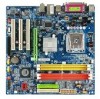
GA-VM800PMC Motherboard Layout KB_MS LGA775 CPU_FAN COMA VGA LPT USB ATX ATX_12V USB GA-VM800PMC Winbond W83627 LAN AUDIO F_AUDIO BIOS VIA VT6103L CD_IN CODEC SUR_CEN COMB SPDIF_IO VIA P4M800 Pro AGP PCI1 PCI2 CLR_CMOS PCI3 BATTERY CI FDD DDRII1 DDRII2 DDR1 DDR2 IDE1 IDE2 VIA - Gigabyte GA-VM800PMC | Manual - Page 8
Block Diagram LGA 775 Processor CPUCLK+/- (200/133 MHz) AGP 4X/8X VGA Port 3 PCI RJ45 VIA 6103L System Bus 800/533 MHz VIA P4M800 Pro 400/333 MHz DDR DDRII 533/400 MHz VIA VT8237R+ 2 Serial ATA LPC BUS Winbond W83627 BIOS Floppy LPT Port AC97 Link PCI CLK (33 MHz) 6 Channel CODEC 8 - Gigabyte GA-VM800PMC | Manual - Page 9
instructions below: 1. Please turn off the computer and unplug its power cord. 2. When handling the motherboard , avoid touching any metal leads or connectors. 3. It is best to wear an electrostatic discharge (ESD) cuff when handling electronic components (CPU motherboard problem manual - Gigabyte GA-VM800PMC | Manual - Page 10
D Š L2 cache varies with CPU Front Side Bus Š Supports 800/533 MHz FSB Chipset Š Northbridge: VIA P4M800 Pro Chipset Š Southbridge: VIA VT8237R+ LAN Š Onboard VIA 6103L chip (10/100 Mbit) Audio Š Onboard VIA 1618 chip Š Supports 2 / 4 / 6 channel audio Š Supports S/PDIF In/Out connection - Gigabyte GA-VM800PMC | Manual - Page 11
Xpress BIOS Rescue Bundle Software Š Norton Internet Security (OEM version) Form Factor Š Micro ATX form factor; 24.4cm x 24.4cm (Note 1) Based on chipset specifications, the GA-VM800PMC can support up to 800 MHz FSB. (Note 2) EasyTune functions may vary depending on different motherboards - Gigabyte GA-VM800PMC | Manual - Page 12
specifications including the CPU, graphics card, memory, hard drive, CPU: An Intel® Pentium 4 Processor with HT Technology - Chipset: An Intel® Chipset that supports HT Technology - BIOS: A BIOS that supports to the CPU during installation.) GA-VM800PMC Motherboard - 12 - Fig. 4 Once the CPU is - Gigabyte GA-VM800PMC | Manual - Page 13
make sure the Male and Female push pin are joined closely. (for detailed installation instructions, please refer to the CPU cooler installation section of the user manual) Fig. 5 Please check the back of motherboard after installing. If the push pin is inserted as the picture, the installation is - Gigabyte GA-VM800PMC | Manual - Page 14
fit in one direction. Insert the DIMM memory module vertically into the DIMM socket. Then push it down. Fig.2 Close the plastic clip at both edges of the DIMM sockets to lock the DIMM module. Reverse the installation steps when you wish to remove the DIMM module. GA-VM800PMC Motherboard - 14 - - Gigabyte GA-VM800PMC | Manual - Page 15
instruction slot in motherboard. 4. BIOS. 8. Install related driver from the operating system. Installing a AGP expansion card: Please carefully pull out the small whitedrawable bar at the end of the AGP slot when you try to install/uninstall the VGA card. Please align the VGA card to the onboard AGP - Gigabyte GA-VM800PMC | Manual - Page 16
port. VGA Port Monitor can be connected to VGA port. driver upgrade. For more information please contact your OS or device(s) vendors. LAN Port The provided Internet connection is Fast Ethernet, supporting audio software to configure 2-/4-/6- channel audio functioning. GA-VM800PMC Motherboard - 16 - - Gigabyte GA-VM800PMC | Manual - Page 17
English 1-7 Connectors Introduction 3 2 1 6 10 7 11 4 13 8 12 15 16 5 17 18 14 9 1) ATX_12V 2) ATX (Power Connector) 3) CPU_FAN 4) SYS_FAN 5) FDD 6) IDE1 / IDE2 7) SATA0 / SATA1 8) F_PANEL 9) PWR_LED 10) F_AUDIO 11) CD_IN 12) SPDIF_IO 13) SUR_CEN 14) F_USB1 / F_USB2 15) COMB 16) CI 17) - Gigabyte GA-VM800PMC | Manual - Page 18
Align the power connector with its proper location on the motherboard and connect tightly. The ATX_12V power connector mainly supplies power to the CPU. If the ATX_12V power connector is not connected, the 12V 3.3V -12V GND PS_ON(soft on/off) GND GND GND -5V +5V +5V GA-VM800PMC Motherboard - 18 - - Gigabyte GA-VM800PMC | Manual - Page 19
connector supplies a +12V power voltage via a 3-pin/4-pin(CPU_FAN) power connector Remember to connect the CPU/system fan cable to the CPU_FAN/SYS_FAN connector to prevent CPU damage or system hanging caused to the FDD drive. The types of FDD drives supported are: 360 KB, 720 KB, 1.2 MB, 1.44 - Gigabyte GA-VM800PMC | Manual - Page 20
via information on settings, please refer to the instructions located on the IDE device). Before BIOS setting for the Serial ATA and install the proper driver in order to work properly. SATA1 1 7 1 7 SATA0 Pin No. 1 2 3 4 5 6 7 Definition GND TXP TXN GND RXN RXP GND GA-VM800PMC Motherboard - Gigabyte GA-VM800PMC | Manual - Page 21
English 8) F_PANEL (Front Panel Connector) Please connect the power LED, PC speaker, reset switch and power switch etc. of your chassis front panel to the F_PANEL connector according to the pin assignments below. Message LED/ Power/ Sleep LED Speaker Connector Power Switch MSG+ MSG- PW+ PWSPEAK+ - Gigabyte GA-VM800PMC | Manual - Page 22
dealer. If you want to use "Front Audio" connector, you must remove the jumpers from pins 5-6, 9-10. 10 9 2 1 Pin No. 1 2 3 4 5 6 7 8 9 10 Definition MIC GND MIC_BIAS POWER FrontAudio(R) Rear Audio (R)/ Return R NC No Pin FrontAudio (L) Rear Audio (L)/ Return L GA-VM800PMC Motherboard - 22 - - Gigabyte GA-VM800PMC | Manual - Page 23
the connector. Pin No. Definition 1 1 CD-L 2 GND 3 GND 4 CD-R 12) SPDIF_IO (S/PDIF In/Out Connector) The S/PDIF output is capable of providing digital audio to external speakers or compressed AC3 data to an external Dolby Digital Decoder. Use this feature only when your stereo system has - Gigabyte GA-VM800PMC | Manual - Page 24
English 13) SUR_CEN (Surround Center Connector) Please contact your nearest dealer for optional 6-Channel Audio Combo Kit. 6 5 2 1 Pin No. 1 2 3 4 5 6 Definition SUR OUTL 8 9 10 Definition Power(5V) Power(5V) USB0 DXUSB1 DyUSB0 DX+ USB1 Dy+ GND GND No Pin NC GA-VM800PMC Motherboard - 24 - - Gigabyte GA-VM800PMC | Manual - Page 25
Intrusion, Case Open) This 2-pin connector allows your system to detect if the chassis cover is removed. You can check the "Case Opened" status in BIOS Setup. Pin No. Definition 1 GND 1 2 Signal - 25 - Hardware Installation - Gigabyte GA-VM800PMC | Manual - Page 26
: Normal Short: Clear CMOS 18) BATTERY GA-VM800PMC Motherboard Danger of explosion if battery is incorrectly replaced. Replace only with the same or equivalent type recommended by the manufacturer. Dispose of used batteries according to the manufacturer's instructions. If you want to erase CMOS - Gigabyte GA-VM800PMC | Manual - Page 27
BIOS, either Gigabyte's Q-Flash or @BIOS utility can be used. Q-Flash allows the user to quickly and easily update or backup BIOS without entering the operating system. @BIOS is a Windows-based utility that does not require users to boot to DOS before upgrading BIOS but directly download and update - Gigabyte GA-VM800PMC | Manual - Page 28
in the BIOS Setup when somehow the system is not stable as usual. This action makes the system reset to the default settings for stability. 3. The BIOS Setup menus described in this chapter are for reference only and may differ from the exact settings for your motherboard. GA-VM800PMC Motherboard - Gigabyte GA-VM800PMC | Manual - Page 29
English „ Standard CMOS Features This setup page includes all the items in standard compatible BIOS. „ Advanced BIOS Features This setup page includes all the items of Award special enhanced features. „ Integrated Peripherals This setup page includes all onboard peripherals. „ Power Management - Gigabyte GA-VM800PMC | Manual - Page 30
3 Mode Support [1.44M, 3.5"] [Disabled] Halt On [All, But Keyboard] Base Memory Extended Memory 640K 447M system start up. • Manual User can manually input the correct settings Access of two methods: • Auto Allows BIOS to automatically detect SATA IDE devices GA-VM800PMC Motherboard - 30 - - Gigabyte GA-VM800PMC | Manual - Page 31
memory installed on the motherboard, or 640K for systems with 640K or more memory installed on the motherboard. Extended Memory The BIOS determines how much extended memory is present during the POST. This is the amount of memory located above 1 MB in the CPU's memory address map. - 31 - BIOS - Gigabyte GA-VM800PMC | Manual - Page 32
BIOS Features Init Display First VGA Share Memory Size ` Hard Disk Boot Priority First Boot Device Second Boot Device Third Boot Device Password Check CPU Hyper-Threading (Note) Limit CPUID Max. to 3 (Note) No-Execute Memory Protect (Note) CPU supports this function. GA-VM800PMC Motherboard - 32 - - Gigabyte GA-VM800PMC | Manual - Page 33
LAN Select your boot device priority by Legacy LAN. supported. (Default value) Disabled Disable CPU Hyper Threading. Limit CPUID Max. to 3 (Note) Enabled Disabled Limit CPUID Maximum value to 3 when use older OS like NT4. Disable CPUID Limit for windows XP. (Default value) No-Execute Memory - Gigabyte GA-VM800PMC | Manual - Page 34
Set onboard SATA mode to IDE. (Default value) AC97 Audio Auto Enable onboard AC'97 audio function. (Default value) Disabled Disable this function. USB 1.1 Controller Disabled Disable USB 1.1 controller. Enabled Enable USB 1.1 controller. (Default value) GA-VM800PMC Motherboard - 34 - - Gigabyte GA-VM800PMC | Manual - Page 35
Enabled Disabled Enable USB mouse support. Disable USB mouse support. (Default value) Legacy USB storage detect This option allows users to decide whether to detect USB storage devices, including USB flash drives and USB hard drives during POST. Enabled BIOS will scan all USB storage devices - Gigabyte GA-VM800PMC | Manual - Page 36
button 4 sec. to Power off. Enter suspend if button is pressed less than 4 sec. AC BACK Function Memory When AC-power back to the system, the system will be back to the last state before AC-power is Key" button, you can press the key to power on the system. GA-VM800PMC Motherboard - 36 - - Gigabyte GA-VM800PMC | Manual - Page 37
function. Enable PME as wake up event. (Default value) Modem Ring Resume An incoming call via modem can awake the system from any suspend state. Disabled Enabled Disable Modem Ring Resume function. Alarm : Everyday, 1~31 Time (hh: mm: ss) Alarm: (0~23) : (0~59) : (0~59) - 37 - BIOS Setup - Gigabyte GA-VM800PMC | Manual - Page 38
) Set IRQ 3,4,5,7,9,10,11,12,14,15 to PCI 2. Auto assign IRQ to PCI 3. (Default value) Set IRQ 3,4,5,7,9,10,11,12,14,15 to PCI 3. GA-VM800PMC Motherboard - 38 - - Gigabyte GA-VM800PMC | Manual - Page 39
Enabled then save BIOS setup and restart your system. Current Voltage(V) VCORE / DDR POWER / +3.3V / +12V Detect system's voltage status automatically. System / CPU Temperature Detect system / CPU temperature automatically. Current SYS / CPU FAN Speed (RPM) Detect system / CPU Fan speed status - Gigabyte GA-VM800PMC | Manual - Page 40
this function. When this function is enabled, CPU fan will run at different speed depending on CPU temperature. Users can adjust the fan speed with Easy Tune based on their requirements. (Default value) (Note) This function is only supported on 4-pin CPU fans. GA-VM800PMC Motherboard - 40 - - Gigabyte GA-VM800PMC | Manual - Page 41
-Copyright (C) 1984-2006 Award Software ` Standard CMOS Features ` Advanced BIOS Features ` Integrated Peripherals ` Power Management Setup ` PnP/PCI Configurations Defaults Selecting this field loads the factory defaults for BIOS and Chipset Features which the system automatically detects. - 41 - Gigabyte GA-VM800PMC | Manual - Page 42
Advance BIOS Features Menu, you will be prompted for the password every time the system is rebooted or any time you try to enter Setup Menu. If you select "Setup" at "Password Check" in Advance BIOS Features Menu, you will be prompted only when you try to enter Setup. GA-VM800PMC Motherboard - 42 - Gigabyte GA-VM800PMC | Manual - Page 43
to Setup Utility. 2-11 Exit Without Saving CMOS Setup Utility-Copyright (C) 1984-2006 Award Software ` Standard CMOS Features ` Advanced BIOS Features ` Integrated Peripherals ` Power Management Setup ` PnP/PCI Configurations ` PC Health Status Load Fail-Safe Defaults Load Optimized Defaults - Gigabyte GA-VM800PMC | Manual - Page 44
English GA-VM800PMC Motherboard - 44 - - Gigabyte GA-VM800PMC | Manual - Page 45
in Windows XP. Insert the driver CD-title that came with your motherboard into your CD-ROM drive, the driver CD-title will auto start and show the installation guide. If not, please double click the CD-ROM device icon in "My computer", and execute the Setup.exe. 3-1 Install Chipset Drivers After - Gigabyte GA-VM800PMC | Manual - Page 46
English 3-2 Software Application This page displays all the tools that Gigabyte developed and some free software. You can click an item to install it. 3-3 Software Information This page lists the contents of software and drivers in this CD-title. GA-VM800PMC Motherboard - 46 - - Gigabyte GA-VM800PMC | Manual - Page 47
English 3-4 Hardware Information This page lists all device you have for this motherboard. 3-5 Contact Us Please see the last page for details. - 47 - Drivers Installation - Gigabyte GA-VM800PMC | Manual - Page 48
English GA-VM800PMC Motherboard - 48 - - Gigabyte GA-VM800PMC | Manual - Page 49
such as 1) Overclocking for enhancing system performance, 2) C.I.A. and M.I.B. for special enhancement for CPU and Memory, 3) Smart-Fan control for managing fan speed control of both CPU cooling fan and North-Bridge Chipset cooling fan, 4) PC health for monitoring system status.(Note) User Interface - Gigabyte GA-VM800PMC | Manual - Page 50
Supporting Microsoft operating systems including Windows XP/2000 64M bytes of system memory 3. VESA-supported VGA cards How to BIOS v6.00PG, An Energy Star Ally Copyright (C) 1984-2006, Award Software, Inc. VM800PMC D5 . . . . :BIOS drivers as well as software. GA-VM800PMC Motherboard - 50 - - Gigabyte GA-VM800PMC | Manual - Page 51
Windows 2000, be sure to execute the EnableBigLba.exe program from the driver CD before data backup. 2. It is normal that data backup takes longer time than data restoration. 3. Xpress Recovery2 is compliant with the GPL regulations. 4. On a few motherboards based on Nvidia chipsets, BIOS update - Gigabyte GA-VM800PMC | Manual - Page 52
Part One. If your motherboard has single-BIOS, please refer to Part Two. Part One: Updating BIOS with Q-FlashTM Utility on Dual BIOS Motherboards. Some of Gigabyte motherboards are equipped with dual BIOS. In the BIOS menu of the motherboards supporting Q-Flash and Dual BIOS, the Q-Flash utility and - Gigabyte GA-VM800PMC | Manual - Page 53
Backup Load Default Settings Save Settings to CMOS Q-Flash Utility Load Main BIOS from Floppy Load Backup BIOS from Floppy Save Main BIOS to Floppy Save Backup BIOS to Floppy Enter : Run :Move ESC:Reset F10:Power Off Dual BIOS utility bar Q-FlashTM utility title bar Action bar Task menu for - Gigabyte GA-VM800PMC | Manual - Page 54
Floppy Save Main BIOS to Floppy Save Backup BIOS to Floppy Enter : Run :Move ESC:Reset F10:Power Off Do not turn off power or reset your system at this stage!! After BIOS file is read, you'll see a confirmation dialog box asking you "Are you sure to update BIOS?" GA-VM800PMC Motherboard - 54 - Gigabyte GA-VM800PMC | Manual - Page 55
Fba after updating. Award Modular BIOS v6.00PG, An Energy Star Ally Copyright (C) 1984-2003, Award Software, Inc. Intel i875P AGPset BIOS for 8KNXP Ultra Fba Check System Health OK , VCore = 1.5250 Main Processor : Intel Pentium(R) 4 1.6GHz (133x12) Memory Testing - Gigabyte GA-VM800PMC | Manual - Page 56
save and exit. Part Two: Updating BIOS with Q-FlashTM Utility on Single-BIOS Motherboards. This part guides users of single-BIOS motherboards how to update BIOS using the Q-FlashTM utility. CMOS : Select Item F10: Save & Exit Setup Time, Date, Hard Disk Type... GA-VM800PMC Motherboard - 56 - - Gigabyte GA-VM800PMC | Manual - Page 57
Q-FlashTM utility Enter : Run Keep DMI Data Enable Update BIOS from Floppy Save BIOS to Floppy :Move ESC:Reset F10:Power Off Action download one BIOS file to the floppy disk so only one BIOS file, 8GE800.F4, is listed. Please confirm again you have the correct BIOS file for your motherboard - Gigabyte GA-VM800PMC | Manual - Page 58
Flash 03/18/2003-I845GE-6A69YG01C-00 6. Press Del to enter BIOS menu after system reboots and load BIOS optimized defaults. See how to load BIOS optimized defaults, please kindly refer to Step 6 to 7 in Part One. Congratulation!! You have updated BIOS successfully!! GA-VM800PMC Motherboard - 58 - - Gigabyte GA-VM800PMC | Manual - Page 59
/ GIGABYTE/@BIOS Fig 4. Select the desired @BIOS server 1. Methods and steps: I. Update BIOS through Internet a. Click "Internet Update" icon b. Click "Update New BIOS" icon c . Select @BIOSTM sever d. Select the exact model name on your motherboard e. System will automatically download and update - Gigabyte GA-VM800PMC | Manual - Page 60
@BIOSTM server, please go onto Gigabyte's web site for downloading and updating it according to method II. IV. Please note that any interruption during updating will cause system unbooted. V. Do not use @BIOS and C.O.M. (Corporate Online Management) at the same time. GA-VM800PMC Motherboard - 60 - - Gigabyte GA-VM800PMC | Manual - Page 61
drive. (b) An empty formatted floppy disk. (c) Windows XP/2000 setup disk. (d) Driver CD for your motherboard. (1) Install SATA hard drive(s) in your system on the motherboard. If there are more than one SATA controller on your motherboard, you may refer to the motherboard user's manual to identify - Gigabyte GA-VM800PMC | Manual - Page 62
F7: Optimized Defaults Figure 1 F1: General Help The BIOS Setup menus described in this section may not show the exact settings for your motherboard. The actual BIOS Setup menu options you will see shall depend on the motherboard you have and the BIOS version. GA-VM800PMC Motherboard - 62 - - Gigabyte GA-VM800PMC | Manual - Page 63
system restarts (Figure 2). CMOS Setup Utility-Copyright (C) 1984-2006 Award Software Advanced BIOS Features Init Display First VGA Share Memory Size Hard Disk Boot Priority First Boot Device Second Boot Device Third Boot Device Password Check CPU Hyper-Threading Limit CPUID Max. to 3 No-Execute - Gigabyte GA-VM800PMC | Manual - Page 64
memory test begins and before the operating system boot begins, the following information will appear on screen (Figure 3). Press the TAB key to enter the VT8237 Serial ATA RAID BIOS configuration utility. VIA Technologies, Inc. VIA VT8237 Serial ATA RAID BIOS 4 GA-VM800PMC Motherboard - 64 - - Gigabyte GA-VM800PMC | Manual - Page 65
a screen similar to Figure 5 below will appear. VIA Tech. VT8237 SATA RAID BIOS Ver 4.97 Auto Setup For Performance Array Mode RAID 0 and press ENTER. And the RAID mode selection menu will appear (Figure 6). The supported RAID modes include RAID 0 for performance, RAID 1 for data protection, and - Gigabyte GA-VM800PMC | Manual - Page 66
manually, you can specify the block size. Use the UP or DOWN ARROW keys to select Block Size and press ENTER. Select the block size from the popup menu. The block size can be set between 4KB to 64KB (Figure 8). VIA Tech. VT8237 SATA RAID BIOS the array creation. GA-VM800PMC Motherboard - 66 - - Gigabyte GA-VM800PMC | Manual - Page 67
array that is to be deleted and press ENTER. A warning message will show up, press Y to confirm or press N to cancel (Figure 9). VIA Tech. VT8237 SATA RAID BIOS Ver 4.97 Create Array Delete Array Create/Delete Spare Select Boot Array Serial Number View The selected array will be destoried. Are you - Gigabyte GA-VM800PMC | Manual - Page 68
screen (Figure 12). VIA Tech. VT8237 SATA RAID BIOS Ver 4.97 Create Array VIA RAID controller F1 : , : Enter : ESC : View Array/disk Status Move to next item Confirm the selection Exit Array Name ARRAY 0 Array Mode Stripe Block Size(GB) 64K Size(GB) 223.58 Figure 12 GA-VM800PMC Motherboard - Gigabyte GA-VM800PMC | Manual - Page 69
recognized during the Windows setup process. First of all, copy the driver for the SATA controller from the motherboard driver CD-ROM to a floppy disk. See the instructions below about how to copy the driver in MS-DOS mode(Note). Prepare a startup disk that has CD-ROM support and a blank formatted - Gigabyte GA-VM800PMC | Manual - Page 70
manufacturer, press S. * If you do not have any device support disks from a mass storage device manufacturer, or do not want to specify additional mass storage devices for use with Windows, press ENTER. S=Specify Additional Device ENTER=Continue F3=Exit Figure 17 GA-VM800PMC Motherboard - 70 - - Gigabyte GA-VM800PMC | Manual - Page 71
Series(Windows XP) VIA V-RAID Controller Series(Windows 2K) VIA V-RAID Controller Series(Windows NT4) ENTER=Select F3=Exit Figure 18 If a message appears saying one or some file(s) cannot be found, please check the floppy disk or copy the correct SATA driver again from the motherboard driver CD - Gigabyte GA-VM800PMC | Manual - Page 72
installing Windows XP, press F3. Enter= Continue R=Repair F3=Exit Figure 20 (Note: Each time you add a new hard drive to a RAID array, the RAID driver will have to be installed under Windows once for that hard drive. After that, the driver will not have to be installed.) GA-VM800PMC Motherboard - Gigabyte GA-VM800PMC | Manual - Page 73
that you use speakers with amplifier to get the best sound effect if the stereo output is applied. STEP 1: Connect the stereo speakers or earphone to "Line Out." Line Out STEP 2: After installing the audio driver, you'll find a VIA Audio Deck icon on the lower right hand taskbar. Double-click - Gigabyte GA-VM800PMC | Manual - Page 74
Channel check box. Line Out Line In When the Environmental Modeling is disable, the sound would be performed as stereo mode (2 Channel output). Please select other settings (ex: Living Room) for 4 Channel output. Select the Enable Environmental Modeling check box. GA-VM800PMC Motherboard - 74 - - Gigabyte GA-VM800PMC | Manual - Page 75
to "MIC In". MIC In Line Out STEP 2: After installing the audio driver, you'll find a VIA Audio Deck icon on the lower right hand taskbar. Double-click the icon to open the Audio Control Panel. Line In STEP 3: In the Audio Control Panel, click the Speaker tab and select the 6 Channel check box - Gigabyte GA-VM800PMC | Manual - Page 76
included in the GIGABYTE unique "6-Channel Audio Combo Kit" as picture. STEP 1: Secure the metal bracket of the"6-Channel Audio Combo Kit" audio panel's "Line Out", the rear channels to SURROUND-Kit's REAR R/L, and the Center/Subwoofer channels to SURROUND-Kit's SUB CENTER. GA-VM800PMC Motherboard - Gigabyte GA-VM800PMC | Manual - Page 77
jack for side surround and red jack for center/LFE speakers output check box. Basic & Advanced 6 Channel Analog Audio Output Mode Notes: When the Environmental Modeling is disable, the sound would be performed as stereo mode (2 Channel output). Please select other settings (ex: Living Room) for - Gigabyte GA-VM800PMC | Manual - Page 78
English 4-2 Troubleshooting Below is a collection of general asked questions. To check general asked questions based on a specific motherboard model, please log on to GIGABYTE's website. Question 1: I cannot see some options that were included in previous BIOS after updating BIOS. Why? Answer: Some - Gigabyte GA-VM800PMC | Manual - Page 79
- 79 - Appendix English - Gigabyte GA-VM800PMC | Manual - Page 80
English GA-VM800PMC Motherboard - 80 - - Gigabyte GA-VM800PMC | Manual - Page 81
- 81 - Appendix English - Gigabyte GA-VM800PMC | Manual - Page 82
English GA-VM800PMC Motherboard - 82 - - Gigabyte GA-VM800PMC | Manual - Page 83
- 83 - Appendix English - Gigabyte GA-VM800PMC | Manual - Page 84
English GA-VM800PMC Motherboard - 84 - - Gigabyte GA-VM800PMC | Manual - Page 85
- 85 - Appendix English - Gigabyte GA-VM800PMC | Manual - Page 86
. 814 Xian TEL: +86-29-85531943 FAX: +86-29-85539821 Shenyang TEL: +86-24-83992901 FAX: +86-24-83992909 y India GIGABYTE TECHNOLOGY (INDIA) LIMITED WEB address : http://www.gigabyte.in y Australia GIGABYTE TECHNOLOGY PTY. LTD. WEB address : http://www.gigabyte.com.au GA-VM800PMC Motherboard - 86 - - Gigabyte GA-VM800PMC | Manual - Page 87
BYTE Technology Co., Ltd. in SERBIA & MONTENEGRO WEB address : http://www.gigabyte.co.yu y GIGABYTE Global Service System To submit a technical or non-technical (Sales/ Marketing) question, please link to : http://ggts.gigabyte.com.tw Then select your language to enter the system. - 87 - Appendix - Gigabyte GA-VM800PMC | Manual - Page 88
- 88 -
-
 1
1 -
 2
2 -
 3
3 -
 4
4 -
 5
5 -
 6
6 -
 7
7 -
8
-
9
-
10
-
11
-
12
-
13
-
14
-
15
-
16
-
17
-
18
-
19
-
20
-
21
-
22
-
23
-
24
-
25
-
26
-
27
-
28
-
29
-
30
-
31
-
32
-
33
-
34
-
35
-
36
-
37
-
38
-
39
-
40
-
41
-
42
-
43
-
44
-
45
-
46
-
47
-
48
-
49
-
50
-
51
-
52
-
53
-
54
-
55
-
56
-
57
-
58
-
59
-
60
-
61
-
62
-
63
-
64
-
65
-
66
-
67
-
68
-
69
-
70
-
71
-
72
-
73
-
74
-
75
-
76
-
77
-
78
-
79
-
80
-
81
-
82
-
83
-
84
-
85
-
86
-
87
-
88
 |
 |

GA-VM800PMC
Intel
®
Core
TM
2 Duo / Intel
®
Pentium
®
D / Pentium
®
4 / Celeron
®
D
LGA775 Processor Motherboard
User's Manual
Rev. 100
3
12ME-VM800PMC-100
3
R
*
The WEEE marking on the product indicates this product must not be disposed of with user's other household waste
and must be handed over to a designated collection point for the recycling of waste electrical and electronic equipment!!
*
The WEEE marking applies only in European Union's member states.