Gigabyte GA-VM800PMC Manual - Page 25
COMB COMB Connector, CI Chassis Intrusion, Case Open
 |
View all Gigabyte GA-VM800PMC manuals
Add to My Manuals
Save this manual to your list of manuals |
Page 25 highlights
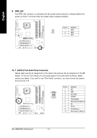
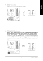
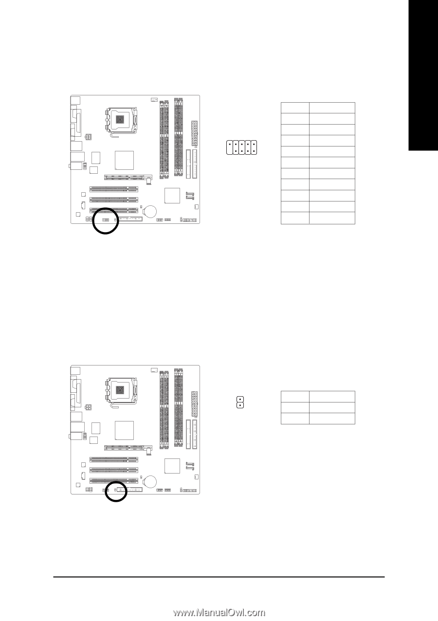
English 15) COMB (COMB Connector) Be careful with the polarity of the COMB connector. Check the pin assignments while you connect the COMB cable. Please contact your nearest dealer for optional COMB cable. 9 1 10 2 Pin No. 1 2 3 4 5 6 7 8 9 10 Definition NDCDBNSINB NSOUTB NDTRBGND NDSRBNRTSBNCTSBNRIBNo Pin 16) CI (Chassis Intrusion, Case Open) This 2-pin connector allows your system to detect if the chassis cover is removed. You can check the "Case Opened" status in BIOS Setup. Pin No. Definition 1 GND 1 2 Signal - 25 - Hardware Installation
-
 1
1 -
2
-
3
-
4
-
5
-
6
-
7
-
8
-
9
-
10
-
11
-
12
-
13
-
14
-
15
-
16
-
17
-
18
-
19
-
 20
20 -
 21
21 -
 22
22 -
 23
23 -
 24
24 -
 25
25 -
 26
26 -
 27
27 -
 28
28 -
 29
29 -
 30
30 -
31
-
32
-
33
-
34
-
35
-
36
-
37
-
38
-
39
-
40
-
41
-
42
-
43
-
44
-
45
-
46
-
47
-
48
-
49
-
50
-
51
-
52
-
53
-
54
-
55
-
56
-
57
-
58
-
59
-
60
-
61
-
62
-
63
-
64
-
65
-
66
-
67
-
68
-
69
-
70
-
71
-
72
-
73
-
74
-
75
-
76
-
77
-
78
-
79
-
80
-
81
-
82
-
83
-
84
-
85
-
86
-
87
-
88
 |
 |
Hardware Installation
- 25 -
English
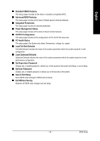
15)
COMB (COMB Connector)
Be careful with the polarity of the COMB connector. Check the pin assignments while you connect
the COMB cable. Please contact your nearest dealer for optional COMB cable.
Pin No.
Definition
1
NDCDB-
2
NSINB
3
NSOUTB
4
NDTRB-
5
GND
6
NDSRB-
7
NRTSB-
8
NCTSB-
9
NRIB-
10
No Pin
10
9
2
1
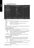
16)
CI (Chassis Intrusion, Case Open)
This 2-pin connector allows your system to detect if the chassis cover is removed. You can check
the "Case Opened" status in BIOS Setup.
1
Pin No.
Definition
1
GND
2
Signal