Gigabyte GA-X58A-UD5 Manual
Gigabyte GA-X58A-UD5 Manual
 |
UPC - 818313009753
View all Gigabyte GA-X58A-UD5 manuals
Add to My Manuals
Save this manual to your list of manuals |
Gigabyte GA-X58A-UD5 manual content summary:
- Gigabyte GA-X58A-UD5 | Manual - Page 1
GA-X58A-UD5 LGA1366 socket motherboard for Intel® Core™ i7 processor family User's Manual Rev. 1001 12ME-X58AUD5-1001R - Gigabyte GA-X58A-UD5 | Manual - Page 2
Motherboard GA-X58A-UD5 Dec. 25, 2009 Motherboard GA-X58A-UD5 Dec. 25, 2009 - Gigabyte GA-X58A-UD5 | Manual - Page 3
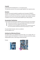
at: http://www.gigabyte.com.tw Identifying Your Motherboard Revision The revision number on your motherboard looks like this: "REV: X.X." For example, "REV: 1.0" means the revision of the motherboard is 1.0. Check your motherboard revision before updating motherboard BIOS, drivers, or when looking - Gigabyte GA-X58A-UD5 | Manual - Page 4
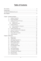
Table of Contents Box Contents...6 Optional Items...6 GA-X58A-UD5 Motherboard Layout 7 Block Diagram...8 Chapter 1 Hardware Installation 9 1-1 Installation Precautions 9 1-2 Product Specifications 10 1-3 Installing the CPU and CPU Cooler 13 1-3-1 Installing the CPU 13 1-3-2 Installing the CPU - Gigabyte GA-X58A-UD5 | Manual - Page 5
3-1 Installing Chipset Drivers 67 3-2 Application Software 68 3-3 Technical Manuals 68 3-4 Contact...69 3-5 System...69 3-6 Download Center 70 3-7 New Utilities...70 Chapter 4 Unique Features 71 4-1 Xpress Recovery2 71 4-2 BIOS Update Utilities 74 4-2-1 Updating the BIOS with the - Gigabyte GA-X58A-UD5 | Manual - Page 6
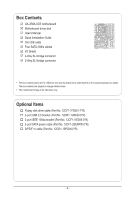
Box Contents GA-X58A-UD5 motherboard Motherboard driver disk User's Manual Quick Installation Guide One IDE cable Four SATA 3Gb/s cables I/O Shield 2-Way SLI bridge connector 3-Way SLI bridge connector • The box contents above are for reference only and - Gigabyte GA-X58A-UD5 | Manual - Page 7
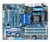
GA-X58A-UD5 PWR_FAN USB_LAN ATX USB30_LAN JMicron JMB362 DDR Voltage LED DDR PHASE LED F_AUDIO NB TEMP L1/2 AUDIO NEC PCIEX1_1(Note 1) RTL8111D PCIEX1_2 RTL8111D NB_FAN SPDIF_I CODEC CD_IN PCI IT8720 SPDIF_O PCIEX8_2 M_BIOS B_BIOS DDR3_2 DDR3_1 DDR3_4 DDR3_3 DDR3_6 DDR3_5 Intel® X58 - Gigabyte GA-X58A-UD5 | Manual - Page 8
Channel Memory x16 x8 PCI Express Bus Switch LAN1 LAN2 QPI Interface Intel® X58 IOH CLK (133 MHz) PCI Express Bus x1 x1 PCIe CLK JMB362 Intel® ICH10R 2 PCI Express x1 x1 2 eSATA 3Gb/s 2 SATA 3Gb/s ATA-133/100/66/33 IDE Channel GIGABYTE SATA2 PCI Bus TSB43AB23 CODEC Dual BIOS 6 - Gigabyte GA-X58A-UD5 | Manual - Page 9
shielding container. • Before unplugging the power supply cable from the motherboard, make sure the power supply has been turned off. • Before turning on the power, make sure the power supply voltage has been set according to the local voltage standard. • Before using the product, please - Gigabyte GA-X58A-UD5 | Manual - Page 10
Specifications CPU Support for an Intel® Core™ i7 series processor in the LGA1366 package (Go to GIGABYTE's website for the latest CPU support list.) L3 cache varies with CPU QPI 4.8GT/s, 6.4GT/s Chipset North Bridge: Intel® X58 Express Chipset South Bridge: Intel® ICH10R Memory - Gigabyte GA-X58A-UD5 | Manual - Page 11
/s devices - Support for SATA RAID 0, RAID 1, and JBOD iTE IT8720 chip: - 1 x floppy disk drive connector supporting up to 1 2 x SATA 6Gb/s connectors w 1 x CPU fan header w 3 x system fan headers w 1 x power fan header w 1 x North Bridge fan header w 1 x front panel header w 1 x front panel - Gigabyte GA-X58A-UD5 | Manual - Page 12
System voltage detection CPU/North Bridge temperature detection CPU/System/Power fan speed detection CPU overheating warning CPU fan fail warning CPU/System fan speed control (Note 4) 2 x 16 Mbit flash Use of licensed AWARD BIOS Support for DualBIOS™ PnP 1.0a, DMI 2.0, SM BIOS 2.4, ACPI 1.0b Support - Gigabyte GA-X58A-UD5 | Manual - Page 13
the CPU and CPU Cooler Read the following guidelines before you begin to install the CPU: • Make sure that the motherboard supports the CPU. (Go to GIGABYTE's website for the latest CPU support list.) • Always turn off the computer and unplug the power cord from the power outlet before installing - Gigabyte GA-X58A-UD5 | Manual - Page 14
B. Follow the steps below to correctly install the CPU into the motherboard CPU socket. Before installing the CPU, make sure to turn off the computer and unplug the power cord from the power outlet to prevent damage to the CPU. CPU Socket Lever Step 1: Completely raise the CPU socket lever. Step - Gigabyte GA-X58A-UD5 | Manual - Page 15
installation manual for instructions on installing the cooler.) Step 5: After the installation, check the back of the motherboard. If the push pin is inserted as the picture above shows, the installation is complete. Step 6: Finally, attach the power connector of the CPU cooler to the CPU fan - Gigabyte GA-X58A-UD5 | Manual - Page 16
motherboard supports the memory. It is recommended that memory of the same capacity, brand, speed, and chips be used. (Go to GIGABYTE's website for the latest memory support list.) • Always turn off the computer and unplug the power cord from the power DDR3_5 Due to chipset limitation, read the Intel - Gigabyte GA-X58A-UD5 | Manual - Page 17
, make sure to turn off the computer and unplug the power cord from the power outlet to prevent damage to the memory module. DDR3 and DDR2 DIMMs are not compatible to each other or DDR DIMMs. Be sure to install DDR3 DIMMs on this motherboard. Notch DDR3 DIMM A DDR3 memory module has a notch, so - Gigabyte GA-X58A-UD5 | Manual - Page 18
motherboard supports the expansion card. Carefully read the manual that came with your expansion card. • Always turn off the computer and unplug the power cord from the power , go to BIOS Setup to make any required BIOS changes for your expansion card(s). 7. Install the driver provided with the - Gigabyte GA-X58A-UD5 | Manual - Page 19
currently supports Windows XP, Windows Vista, and Windows 7 operating systems - The 3-Way CrossFireX/SLI technology currectly supports Windows Vista and Windows 7 operating systems only - A CrossFireX/SLI-supported motherboard with two/three PCI Express x16 slots and correct driver - Two - Gigabyte GA-X58A-UD5 | Manual - Page 20
, USB flash drive and etc. eSATA/USB Combo Connector This connector supports SATA 3Gb/s and USB 2.0/1.1 specification. Use the port to connect an first remove the cable from your device and then remove it from the motherboard. • When removing the cable, pull it straight out from the connector - Gigabyte GA-X58A-UD5 | Manual - Page 21
USB 3.0/2.0 Port The USB 3.0 port supports the USB 3.0 specification and is compatible to the USB 2.0/1.1 specification. Use this port for be connected to the default Mic in jack ( ). Refer to the instructions on setting up a 2/4/5.1/7.1-channel audio configuration in Chapter 5, "Configuring - Gigabyte GA-X58A-UD5 | Manual - Page 22
, yellow) L3: Level 3 (High, red) SB Voltage Off: Normal condition L1: Level 1 (Slight, green) L2: Level 2 (Moderate, yellow) L3: Level 3 (High, red) Overclock LEDs The onboard CPU overclock LEDs indicate on which level the CPU is overclocked. The higher the overclock level, the more the number of - Gigabyte GA-X58A-UD5 | Manual - Page 23
Switches This motherboard has 2 quick buttons: power button and reset button. The power button and reset button allow users to quickly turn on/off or reset the computer in an open-case environment when they want to change hardware components or conduct hardware testing. PW_SW: Power switch RST_SW - Gigabyte GA-X58A-UD5 | Manual - Page 24
DDR PHASE LED The number of lighted LEDs indicates the memory loading. The higher the memory loading, the more the number of lighted LEDs. Hardware Installation - 24 - - Gigabyte GA-X58A-UD5 | Manual - Page 25
with the connectors you wish to connect. • Before installing the devices, be sure to turn off the devices and your computer. Unplug the power cord from the power outlet to prevent damage to the devices. • After installing the device and before turning on the computer, make sure the device cable has - Gigabyte GA-X58A-UD5 | Manual - Page 26
are compatible with power supplies with 2x2 12V and 2x10 power connectors. When using a power supply providing a 2x4 12V and a 2x12 power connector, remove the protective covers from the 12V power connector and the main power connector on the motherboard. Do not insert the power supply cables - Gigabyte GA-X58A-UD5 | Manual - Page 27
) system fan headers, and a 3-pin power fan header (PWR_FAN). Most fan headers possess a foolproof insertion design. When connecting a fan cable, be sure to connect it in the correct orientation (the black connector wire is the ground wire). The motherboard supports CPU fan speed control, which - Gigabyte GA-X58A-UD5 | Manual - Page 28
to connect a floppy disk drive. The types of floppy disk drives supported are: 360 KB, 720 KB, 1.2 MB, 1.44 MB, and 2.88 MB. Before connecting a floppy disk drive, be sure to locate pin the IDE devices, read the instructions from the device manufacturers.) 39 1 40 2 Hardware Installation - 28 - - Gigabyte GA-X58A-UD5 | Manual - Page 29
to SATA 3Gb/s standard and are compatible with SATA 1.5Gb/s standard. Each SATA connector supports a single SATA device. The GIGABYTE SATA2 controller supports RAID 0, RAID 1, and JBOD. Refer to Chapter 5, "Configuring SATA Hard Drive(s)," for instructions on configuring a RAID array. GSATA2_9 - Gigabyte GA-X58A-UD5 | Manual - Page 30
compatible with SATA 3Gb/s and SATA 1.5Gb/s standards. Each SATA connector supports a single SATA device. The Marvell 9128 supports RAID 0 and RAID 1. Refer to Chapter 5, "Configuring SATA Hard Drive(s)," for instructions on configur- ing a RAID power to keep the values (such as BIOS - Gigabyte GA-X58A-UD5 | Manual - Page 31
positive and negative pins before connecting the cables. Message/Power/ Power Sleep LED Switch Speaker MSG+ MSG- PW+ PWSPEAK problem is detected at system startup. If a problem is detected, the BIOS may issue beeps in different patterns to indicate the problem. Refer to Chapter 5, "Troubleshooting - Gigabyte GA-X58A-UD5 | Manual - Page 32
The front panel audio header supports Intel High Definition audio (HD) and AC'97 audio. You may connect your chassis front panel audio module to this header. Make sure the wire assignments of the module connector match the pin assignments of the motherboard header. Incorrect connection between the - Gigabyte GA-X58A-UD5 | Manual - Page 33
Power 1 2 SPDIFI 3 GND 17) SPDIF_O (S/PDIF Out Header) This header supports digital S/PDIF Out and connects a S/PDIF digital audio cable (provided by expansion cards) for digital audio output from your motherboard carefully read the manual for your expansion card. 1 Pin No. Definition 1 - Gigabyte GA-X58A-UD5 | Manual - Page 34
can provide two USB ports via an optional USB bracket. For purchasing the optional USB bracket, please contact the local dealer. Pin No. Definition 1 Power (5V) 9 1 2 Power (5V) 10 2 3 USB DX- G.QBOF4M USB DY- 5 USB DX+ 6 USB DY+ 7 GND 8 GND 9 No Pin 10 NC • Do not plug the IEEE 1394 - Gigabyte GA-X58A-UD5 | Manual - Page 35
- 35 - Hardware Installation - Gigabyte GA-X58A-UD5 | Manual - Page 36
Hardware Installation - 36 - - Gigabyte GA-X58A-UD5 | Manual - Page 37
the GIGABYTE Q-Flash or @BIOS utility. • Q-Flash allows the user to quickly and easily upgrade or back up BIOS without entering the operating system. • @BIOS is a Windows-based utility that searches and downloads the latest version of BIOS from the Internet and updates the BIOS. For instructions on - Gigabyte GA-X58A-UD5 | Manual - Page 38
v6.00PG, An Energy Star Ally Copyright (C) 1984-2009, Award Software, Inc. Motherboard Model BIOS Version X58A-UD5 E4c . . . . : BIOS Setup : XpressRecovery2 : Boot Menu : Qflash 12/08/2009-X58-ICH10-7A89QG0JC-00 Function Keys Function Keys Function Keys: : POST SCREEN - Gigabyte GA-X58A-UD5 | Manual - Page 39
BIOS Version: E4c) CMOS Setup Utility-Copyright (C) 1984-2009 Award Software MB Intelligent Tweaker(M.I.T.) Standard CMOS Features Advanced BIOS Features Integrated Peripherals Power CPU's Clock & Voltage F11: Save CMOS to BIOS F12: Load CMOS from BIOS BIOS Setup Program Function Keys - Gigabyte GA-X58A-UD5 | Manual - Page 40
BIOS settings. First select the profile you wish to load, then press to complete. MB Intelligent Tweaker(M.I.T.) Use this menu to configure the clock, frequency and voltages integrated LAN, etc. Power Management Setup Use this menu to configure all the power-saving functions. PC - Gigabyte GA-X58A-UD5 | Manual - Page 41
MB (SPD) Profile DDR Voltage Profile QPI Voltage >>>>> Channel A x 1984-2009 Award Software MB Intelligent Tweaker(M.I.T.) x tRP [Press Enter] Voltage Types Normal Current overclock/overvoltage may result in damage to CPU, chipset supports this feature. (Note 2) This item appears only - Gigabyte GA-X58A-UD5 | Manual - Page 42
Tech. Allows you to determine whether to enable the Intel CPU Turbo Boost technology. (Default: Enabled) (Note) This item is present only if you install a CPU that supports this feature. For more information about Intel CPUs' unique features, please visit Intel's website. BIOS Setup - 42 - - Gigabyte GA-X58A-UD5 | Manual - Page 43
(Note) Enables or disables Intel CPU Enhanced Halt (C1E) function, a CPU power-saving function in system halt state. When enabled, the CPU core frequency and voltage will be reduced during system halt state to decrease power consumption. (Default: Enabled) C3/C6/C7 State Support (Note) Allows you to - Gigabyte GA-X58A-UD5 | Manual - Page 44
Clock Ratio Displays the Uncore clock ratio. Options are: Auto (default), x12~x48. Isochronous Support Determines whether to enable specific streams between the IOH and ICH. (Default: Enabled) ******** F6: Fail-Safe Defaults ESC: Exit F1: General Help F7: Optimized Defaults BIOS Setup - 44 - - Gigabyte GA-X58A-UD5 | Manual - Page 45
be configurable. Note: If your system fails to boot after overclocking, please wait for 20 seconds to allow for automated system reboot, the CPU specifications. PCI Express Frequency(Mhz) Allows you to manually set the PCIe clock frequency. The adjustable range is from 90 45 - BIOS Setup - Gigabyte GA-X58A-UD5 | Manual - Page 46
) Profile DDR Voltage Profile QPI Voltage x Channel Interleaving (X.M.P.) (Note) Allows the BIOS to read the SPD data Auto (default), Quick, Expert. Profile DDR Voltage When using a non-XMP memory module or the XMP memory. Profile QPI Voltage The value displayed here is dependent on the CPU - Gigabyte GA-X58A-UD5 | Manual - Page 47
Control tRC Options are: Auto (default), 1~63. tRRD Options are: Auto (default), 1~7. tWTR Options are: Auto (default), 1~31. tWR Options are: Auto (default), 1~15. - 47 - BIOS Setup - Gigabyte GA-X58A-UD5 | Manual - Page 48
>>>>> Channel A/B/C Reads Followed by Reads Different DIMMs Options are: Auto (default), 1~8. Different Ranks Options are: Auto (default), 1~8. On The Same Rank Options are: Auto (default), 1~2. BIOS Setup - 48 - ESC: Exit F1: General Help F7: Optimized Defaults - Gigabyte GA-X58A-UD5 | Manual - Page 49
F1: General Help F7: Optimized Defaults CMOS Setup Utility-Copyright (C) 1984-2009 Award Software Advanced Voltage Control Ch-A Address VRef. Ch-B Address VRef. Ch-C Address VRef. 0.750V 0.750V 0.750V Safe Defaults ESC: Exit F1: General Help F7: Optimized Defaults - 49 - BIOS Setup - Gigabyte GA-X58A-UD5 | Manual - Page 50
Calibration may keep the CPU voltage more constant under light and heavy CPU load. Standard Disables Load-Line Calibration and sets VDroop following Intel specifications. (De- fault) Level -B Address VRef. The default is Auto. Ch-C Address VRef. The default is Auto. BIOS Setup - 50 - - Gigabyte GA-X58A-UD5 | Manual - Page 51
the IDE/SATA device on this channel. IDE Channel 0, 1 Master/Slave Configure your IDE/SATA devices by using one of the three methods below: - 51 - BIOS Setup - Gigabyte GA-X58A-UD5 | Manual - Page 52
Lets the BIOS automatically detect IDE/SATA devices during the POST. (Default) • None If no IDE/SATA devices are used, set this item to None so the system will skip the detection of the device during the POST for faster system startup. • Manual Allows you to manually enter the - Gigabyte GA-X58A-UD5 | Manual - Page 53
hard drive and to issue warnings when a third party hardware monitor utility is installed. (Default: Disabled) (Note) This item is present only if you install a CPU that supports this feature. For more information about Intel CPUs' unique features, please visit Intel's website. - 53 - BIOS Setup - Gigabyte GA-X58A-UD5 | Manual - Page 54
XP operating system; set this item to Enabled for legacy operating system such as Windows NT4.0. (Default: Disabled) No-Execute Memory Protect (Note) Enables or disables Intel Execute Disable Bit function. This function may enhance protection for the computer, reducing exposure to viruses and - Gigabyte GA-X58A-UD5 | Manual - Page 55
GSATA 6_7/IDE Ctrl Mode GSATA RAID Configuration GSATA 8_9/IDE Controller GSATA RAID(XHD) automatically. For details on using the GIGABYTE X.H.D utility, refer to Chaper 4, "eXtreme Hard Drive (X.H.D)." (Default: Disabled) ICH SATA Control Mode (Intel ICH10R Chipset) Enables or disables RAID - Gigabyte GA-X58A-UD5 | Manual - Page 56
driver to enable advanced Serial ATA features such as Native Command Queuing and hot plug. SATA Port0-3 Native Mode (Intel Disabled if you wish to install operating systems that do not support Native mode. (Default) Enabled Allows the SATA controllers to : Disabled) BIOS Setup - 56 - - Gigabyte GA-X58A-UD5 | Manual - Page 57
motherboard incorporates cable diagnostic feature designed to detect the status of the attached LAN cable. This feature will detect cabling issue 100/1000 Mbps in Windows mode or when the LAN Boot ROM is activated. When a Cable Problem Occurs... If a cable problem occurs on a 57 - BIOS Setup - Gigabyte GA-X58A-UD5 | Manual - Page 58
RAID for the Marvell 9128 SATA controller. Refer to Chapter 5, "Configuring SATA Hard Drive(s)," for instructions on configuring a RAID array. GSATA 8_9/IDE Controller (GIGABYTE driver to enable advanced Serial ATA features such as Native Command Queuing and hot plug. RAID/IDE Enables RAID - Gigabyte GA-X58A-UD5 | Manual - Page 59
supply providing at least 1A on the +5VSB lead. (Default: Enabled) Power On by Ring Allows the system to be awakened from an ACPI sleep state by a wake-up signal from a modem that supports wake-up function. (Default: Enabled) (Note) Supported on Windows 7/Vista operating system only. - 59 - BIOS - Gigabyte GA-X58A-UD5 | Manual - Page 60
select 64-bit mode when you install 64-bit Windows Vista. This item is configurable only if the HPET Support is set to Enabled. (Default: 32-bit mode) Power On By Mouse Allows the system to be turned on by a PS/2 mouse wake-up event. Note: To use this function, you need an ATX power supply providing - Gigabyte GA-X58A-UD5 | Manual - Page 61
detection status of the chassis intrusion detection device attached to the motherboard CI header. If the system chassis cover is removed, voltages. Current CPU/MCH Temperature Displays current CPU/North Bridge temperature. Current CPU/SYSTEM/POWER FAN Speed (RPM) Displays current CPU/system/power - Gigabyte GA-X58A-UD5 | Manual - Page 62
3-pin CPU fan. PWM Sets PWM mode for a 4-pin CPU fan. Note: The Voltage mode can be set for a 3-pin CPU fan or a 4-pin CPU fan. However, for a 4-pin CPU fan that is not designed following Intel PWM fan specifications, selecting PWM mode may not effectively reduce the fan speed. BIOS Setup - 62 - - Gigabyte GA-X58A-UD5 | Manual - Page 63
to load Fail-Safe defaults, which are the safest and most stable BIOS settings for the motherboard. 2-10 Load Optimized Defaults CMOS Setup Utility-Copyright (C) 1984-2009 Award Software MB Intelligent Tweaker(M.I.T.) Load Fail-Safe Defaults Standard CMOS Features Load Optimized Defaults - Gigabyte GA-X58A-UD5 | Manual - Page 64
2-11 Set Supervisor/User Password CMOS Setup Utility-Copyright (C) 1984-2009 Award Software MB Intelligent Tweaker(M.I.T.) Standard CMOS Features Advanced BIOS Features Integrated Peripherals Power Management SetupEnter Password: PC Health Status Load Fail-Safe Defaults Load Optimized - Gigabyte GA-X58A-UD5 | Manual - Page 65
-2009 Award Software MB Intelligent Tweaker(M.I.T.) Load Fail-Safe Defaults Standard CMOS Features Advanced BIOS Features Load Optimized Defaults Save to CMOS and EXITSe(Yt S/Nup)?erYvisor Password Integrated Peripherals Set User Password Power - Gigabyte GA-X58A-UD5 | Manual - Page 66
BIOS Setup - 66 - - Gigabyte GA-X58A-UD5 | Manual - Page 67
recommended drivers. Or click Install Single Items to manually select the drivers instructions to restart your system. You can install other applications included in the motherboard driver disk. • For USB 2.0 driver support under the Windows XP operating system, please install the Windows XP Service - Gigabyte GA-X58A-UD5 | Manual - Page 68
applications that GIGABYTE develops and some free software. You can click the Install button on the right of an item to install it. 3-3 Technical Manuals This page provides GIGABYTE's application guides, content descriptions for this driver disk, and the motherboard manuals. Drivers Installation - Gigabyte GA-X58A-UD5 | Manual - Page 69
3-4 Contact For the detailed contact information of the GIGABYTE Taiwan headquarter or worldwide branch offices, click the URL on this page to link to the GIGABYTE website. 3-5 System This page provides the basic system information. - 69 - Drivers Installation - Gigabyte GA-X58A-UD5 | Manual - Page 70
3-6 Download Center To update the BIOS, drivers, or applications, click the Download Center button to link to the GIGABYTE website. The latest version of the BIOS, drivers, or applications will be displayed. 3-7 New Utilities This page provides a quick link to GIGABYTE's lately developed utilities - Gigabyte GA-X58A-UD5 | Manual - Page 71
and drivers are installed. • The amount of data and hard drive access speed may affect the speed at which the data is backed up/ restored. • It takes longer to back up a hard drive than to restore it. System Requirements: • At least 512 MB of system memory • VESA compatible graphics card • Windows - Gigabyte GA-X58A-UD5 | Manual - Page 72
note that if there is no enough unallocated space, Xpress Recovery2 cannot save the backup file. B. Accessing Xpress Recovery2 1. Boot from the motherboard driver disk to access Xpress Recovery2 for the first time. When you see the following message: Press any key to startup Xpress Recovery2, press - Gigabyte GA-X58A-UD5 | Manual - Page 73
D. Using the Restore Function in Xpress Recovery2 Select RESTORE to restore the backup to your hard drive in case the system breaks down. The RESTORE option will not be present if no backup is created before. E. Removing the Backup Step 1: If you wish to remove the backup file, select REMOVE. Step - Gigabyte GA-X58A-UD5 | Manual - Page 74
However, if the BIOS update file is saved to a hard drive in RAID/AHCI mode or a hard drive attached to an independent IDE/SATA controller, use the key during the POST to access Q-Flash. Award Modular BIOS v6.00PG, An Energy Star Ally Copyright (C) 1984-2009, Award Software, Inc. X58A-UD5 E4c - Gigabyte GA-X58A-UD5 | Manual - Page 75
Drive Enter : Run hi:Move ESC:Reset F10:Power Off Total size : 0 Free size : 0 3. Select the BIOS update file and press . Make sure the BIOS update file matches your motherboard model. Step 2: The process of the system reading the BIOS file from the floppy disk is displayed on the - Gigabyte GA-X58A-UD5 | Manual - Page 76
Defaults and press to load BIOS defaults. System will re-detect all peripheral devices after a BIOS update, so we recommend that you reload BIOS defaults. CMOS Setup Utility-Copyright (C) 1984-2009 Award Software MB Intelligent Tweaker(M.I.T.) Load Fail-Safe Defaults Standard - Gigabyte GA-X58A-UD5 | Manual - Page 77
. If the BIOS update file for your motherboard is not present on the @BIOS server site, please manually download the BIOS update file from GIGABYTE's website and follow the instructions in "Update the BIOS without Using the Internet Update Function" below. 2. Update the BIOS without Using the - Gigabyte GA-X58A-UD5 | Manual - Page 78
you to monitor hardware temperature, voltage and fan speed and set motherboard model. Grayed-out area(s) indicates that the item is not configurable or the function is not supported. Incorrectly doing overclock/overvoltage may result in damage to the hardware components such as CPU, chipset - Gigabyte GA-X58A-UD5 | Manual - Page 79
design, GIGABYTE Dynamic Energy SaverTM 2 is able to provide exceptional power savings and enhanced power efficiency without Update (Check for the latest utility version) • The above data is for reference only. Actual performance may vary depending on motherboard model. • CPU Power and Power - Gigabyte GA-X58A-UD5 | Manual - Page 80
to run in taskbar) 13 INFO/Help 14 Motherboard Phase LED On/Off Switch (Default: On) 15 Live Utility Update (Check for the latest utility version) C. Stealth Mode In Stealth Mode, the system continues to work with the user-defined power saving settings, even after the system is restarted - Gigabyte GA-X58A-UD5 | Manual - Page 81
for using Q-Share After installing Q-Share from the motherboard driver disk, go to Start>All Programs>GIGABYTE>Q-Share.exe to launch the Q-Share tool. Find shared data folder Changes the data folder to be shared (Note) Updates Q-Share online Displays the current Q-Share version Exits Q-Share ( - Gigabyte GA-X58A-UD5 | Manual - Page 82
4-6 Smart 6™ GIGABYTE Smart 6™ (Note 1) is designed with user-friendliness in mind, and Instructions: Select the Enable check box below the BIOS QuickBoot or OS QuickBoot item and then click Save to save the settings. SMART QuickBoost SMART QuickBoost features quick and effortless CPU overclocking - Gigabyte GA-X58A-UD5 | Manual - Page 83
system) in Windows Vista. Instructions: In 64 backups (the actual limit depends on the size of each partition). When this limit is reached, the oldest backup will be ovewritten. Instructions BIOS simultaneously, which can prevent loss of the data in case the system/hard drive fails. Instructions - Gigabyte GA-X58A-UD5 | Manual - Page 84
data files were moved within the hard drive or copied to an external storage device. Instructions: Select the Enable check box at the bottom of the On/Off Recorder or File the User Password in the system BIOS Setup program to prevent the system time being changed by other users. Unique Features - 84 - Gigabyte GA-X58A-UD5 | Manual - Page 85
Green main menu and click Save to save the settings. Button Standby Suspend Disable Description Enters Power on Suspend mode Enters Suspend to RAM mode Disables this function The Bluetooth dongle included in the motherboard package(Note 2) allows you to wake up the system from Suspend to - Gigabyte GA-X58A-UD5 | Manual - Page 86
1: Configure the system BIOS Enter the system BIOS Setup program, set eXtreme Hard Drive (X.H.D) under the Integrated Peripherals menu to Enabled to enable RAID for the Intel SATA controllers. Step 2: Install the RAID driver and operating system The X.H.D utility supports Windows 7/Vista/XP. Before - Gigabyte GA-X58A-UD5 | Manual - Page 87
- work switch or router device supports the IEEE 802.3ad LACP standard. Please refer to your network switch or router device manual for further details. Select Realtek Ethernet Diagnostic Utility and click Install. Step 1: Insert the motherboard driver disk and select Application Software, Install - Gigabyte GA-X58A-UD5 | Manual - Page 88
Unique Features - 88 - - Gigabyte GA-X58A-UD5 | Manual - Page 89
to identify the SATA controller for the SATA port. (For example, on this motherboard, the SATA2_0, SATA2_1, SATA2_2, SATA2_3, SATA2_4 and SATA2_5 ports are supported by ICH10R Chipset.) Then connect the power connector from your power supply to the hard drive. (Note 1) Skip this step if you do not - Gigabyte GA-X58A-UD5 | Manual - Page 90
1: Turn on your computer and press to enter BIOS Setup during the POST (Power-On Self-Test). To create RAID, set ICH SATA Control Mode under the Integrated Peripherals menu to RAID(XHD) (Figure 1) (IDE by default). If you do not want to create RAID, set this item to IDE or AHCI. CMOS Setup - Gigabyte GA-X58A-UD5 | Manual - Page 91
RAID array in RAID BIOS Enter the RAID BIOS setup utility to configure a RAID array. Skip this step and proceed with the installation of Windows operating system for a non-RAID Create RAID Volume If you want to create a RAID array, select Create RAID Volume in MAIN MENU and press . Intel(R) - Gigabyte GA-X58A-UD5 | Manual - Page 92
4). RAID levels supported include RAID 0, RAID 1, Recovery, RAID 10, and RAID 5 (the selections available depend on the number of the hard drives being installed). Press to proceed. Intel(R) Matrix Storage Manager option ROM v8.9.0.1023 PCH-D wRAID5 Copyright(C) 2003-09 Intel Corporation - Gigabyte GA-X58A-UD5 | Manual - Page 93
(0) Member Disk(0) [hi]-Select [ESC]-Exit Figure 7 [ENTER]-Select Menu To exit the RAID BIOS utility, press or select 5. Exit in MAIN MENU. Now, you can proceed to create the SATA RAID/AHCI driver diskette and install the SATA RAID/AHCI driver and operating system. - 93 - Appendix - Gigabyte GA-X58A-UD5 | Manual - Page 94
option ROM v8.9.0.1023 PCH-D wRAID5 Copyright(C) 2003-09 Intel Corporation. All Rights Reserved. [ MAIN MENU ] 1. Create RAID Volume 2. Delete RAID Volume 5. Exit 3. Reset Disks to Non-RAID 4. Recovery Volume Options RAID Volumes : None defined. [ DISK/VOLUME INFORMATION ] Physical Disks - Gigabyte GA-X58A-UD5 | Manual - Page 95
(C) 2003-09 Intel Corporation. All Rights Reserved. [ CREATE VOLUME MENU ] Name : Volume0 RAID Level : Recovery Disks : Select Disks Strip Size : N/A Capacity : 0.0 GB Sync : Continuous Create Volume [ HELP ] Select a sync option: On Request: volume is updated manually Continuous: volume - Gigabyte GA-X58A-UD5 | Manual - Page 96
a RAID array, select Delete RAID Volume in MAIN MENU and press . In the DELETE VOLUME MENU section, use the up or down arrow key to select the array to be deleted and press . When prompted to confirm your selection (Figure 12), press to confirm or to abort. Intel(R) Matrix - Gigabyte GA-X58A-UD5 | Manual - Page 97
end to available SATA port on the motherboard. See the table below for the SATA controllers and their corresponding SATA ports. Then connect the power connector from your power supply to the hard drive. B. Configuring SATA controller mode in BIOS Setup Make sure to configure the SATA controller - Gigabyte GA-X58A-UD5 | Manual - Page 98
C. Configuring a RAID array in RAID BIOS Enter the RAID BIOS setup utility to configure a RAID array. Skip this step and proceed to the installation of Windows operating system for a non-RAID configuration. After the POST memory test begins and before the operating system boot begins, look for a - Gigabyte GA-X58A-UD5 | Manual - Page 99
Array: In the main screen, press on the Create RAID Disk Drive item. Then the Create New RAID screen appears (Figure 4). Gigabyte Technology Corp. RAID Setup Utility v1.07.06 [ Create New RAID ] Name: Level: Disks: Block: Size: GRAID_ 0-Stripe Select Disk 128 KB 240 GB [ Hard Disk - Gigabyte GA-X58A-UD5 | Manual - Page 100
Disks: After a RAID mode is selected, RAID BIOS automatically assigns the two hard drives installed as the RAID drives. 4. Set Block Size (RAID 0 only): Under to confirm or to abort. Gigabyte Technology Corp. RAID Setup Utility v1.07.06 [ Create New RAID ] Name: Level: Disks: Block: Size - Gigabyte GA-X58A-UD5 | Manual - Page 101
array and press . A small window displaying the array information will appear in the center of the screen (Figure 9). Gigabyte Technology Corp. RAID Setup Utility v1.07.06 [ Main Menu ] Create RAID Disk Drive Delete RAID Disk Drive Revert HDD to Non-RAID Solve Mirror Conflict Rebuild Mirror - Gigabyte GA-X58A-UD5 | Manual - Page 102
GB Normal Members(HDDx) 01 [fgTAB]-Switch Window [hi]-Select ITEM Figure 10 [ENTER]-Action [ESC]-Exit Now, you may proceed to create the SATA RAID/AHCI driver diskette and the installation of the SATA RAID/ AHCI driver and operating system. Delete the RAID Array: To delete the array, select - Gigabyte GA-X58A-UD5 | Manual - Page 103
end to available SATA port on the motherboard. The Marvell 9128 SATA controller controls the GSATA3_6/7 ports on the motherboard. Then connect the power connector from your power supply to the hard drive. B. Configuring SATA controller and RAID mode in BIOS Setup Make sure to configure the SATA - Gigabyte GA-X58A-UD5 | Manual - Page 104
22L PD 8: WDC WD800JD-22L Information Vendor ID : Device ID : Revision ID : BIOS Version : Firmware Version : PCIe Speed rate : Configure SATA as : 1B4B 91A3 B1 1.0.0.1006 2.1.0.1314 2.56Gbps IDE Mode Help Marvell RAID on chip controller. ENTER: Operation F10: Exit/Save ESC: Return Figure - Gigabyte GA-X58A-UD5 | Manual - Page 105
). Marvell BIOS Setup (c) 2009 Marvell Technology Group Ltd. Configure -> Select free disksCreate Virtual Disk HBA 0 : Marvell 0 Virtual Disks Free Physical Disks * PD 0: WDC WD800JD-22L * PD 8: WDC WD800JD-22L RAID Level : Max Size (MB) : Stripe Size : Gigabyte Rounding : Quick - Gigabyte GA-X58A-UD5 | Manual - Page 106
WD800JD-22L Free Physical Disks Information Vendor ID : Device ID : Revision ID : BIOS Version : Firmware Version : PCIe Speed rate : Configure SATA as : 1B4B 91A3 B1 1.0.0.1006 2.1.0.1314 2.56Gbps IDE Mode Help Marvell RAID on chip controller. ENTER: Operation F10: Exit/Save ESC: Return - Gigabyte GA-X58A-UD5 | Manual - Page 107
Disks Delete Virtual Disk Information Vendor ID : Device ID : Revision ID : BIOS Version : Firmware Version : PCIe Speed rate : Configure SATA as , insert the motherboard driver disk, then go to Application Software\Install GIGABYTE Utilities and select Marvell Raid Utility to install - Gigabyte GA-X58A-UD5 | Manual - Page 108
JMB362/GIGABYTE SATA2, type (Figure 2): (Note 1) A:\>copy d:\bootdrv\gsata\32bit\*.* • For the Marvell 9128, type (Figure 3): (Note 2) A:\>copy d:\bootdrv\Marvell\win32\*.* Figure 1 Figure 2 Figure 3 (Note 1) Change the directory from \32bit to \64bit for copying the Windows 64-bit driver - Gigabyte GA-X58A-UD5 | Manual - Page 109
>. For example, from the menu in Figure 5, • For the Intel ICH10R, select 1) Intel Matrix Storage driver for 32bit system for Windows XP operating system. • For the JMicron JMB362, select 3) GIGABYTE GSATA driver for 32bit system for Windows 32-bit op- erating system. • For the Marvell 9128 , select - Gigabyte GA-X58A-UD5 | Manual - Page 110
if you need to install a 3rd party SCSI or RAID driver" (Figure 1). A screen will then appear asking you to specify additional device. Windows Setup Press F6 if you need to install a third party SCSI or RAID driver. Figure 1 Step 2: For the Intel ICH10R: Insert the floppy disk containing the SATA - Gigabyte GA-X58A-UD5 | Manual - Page 111
SATA2: Insert the floppy disk containing the SATA RAID/AHCI driver and press . Then a controller menu similar to Figure 3 below will appear. Select RAID/AHCI Driver for GIGABYTE GBB36X Controller (x32) and press . Windows Setup You have chosen to configure a SCSI Adapter for use with - Gigabyte GA-X58A-UD5 | Manual - Page 112
iMSM folder to the USB flash drive). Then use Method B to load the driver. Method A: Insert the motherboard driver disk into your system and browse to the following directory: \BootDrv\iMSM\32Bit For Windows Vista 64-bit, browse to the 64Bit folder. Method B: Insert the USB flash drive containing - Gigabyte GA-X58A-UD5 | Manual - Page 113
Step 3: When a screen as shown in Figure 7 appears, select Intel(R) ICH8R/ICH9R/ICH10R/DO/PCH SATA RAID Controller and click Next. Figure 7 Step 4: After the driver is loaded, select the RAID/AHCI drive(s) where you want to install the operating system and then click Next to continue the OS - Gigabyte GA-X58A-UD5 | Manual - Page 114
GSATA folder to the USB flash drive). Then use Method B to load the driver. Method A: Insert the motherboard driver disk into your system and browse to the following directory: \BootDrv\GSATA\32Bit For Windows Vista 64-bit, browse to the 64Bit folder. Method B: Insert the USB flash drive containing - Gigabyte GA-X58A-UD5 | Manual - Page 115
Step 3: When a screen as shown in Figure 11 appears, select GIGABYTE GBB36X Controller and click Next. Figure 11 Step 4: After the driver is loaded, select the RAID/AHCI drive(s) where you want to install the operating system and then click Next to continue the OS installation (Figure 12). Figure - Gigabyte GA-X58A-UD5 | Manual - Page 116
performed after you enter the operating system (look for the Intel Storage Console icon in the notification area, which will show that a RAID volume is being rebuilt). If you do not enable automatic rebuild on this stage, you have to manually rebuild the array in the operating system (see the next - Gigabyte GA-X58A-UD5 | Manual - Page 117
chipset driver has been installed from the motherboard driver disk. Then launch the Intel Matrix Storage Console from All Programs in the Start menu. Step 1: On the View menu of the Intel Click Next when the Rebuild RAID Volume Wizard appears. Follow the on-screen instructions to proceed. Step 4: - Gigabyte GA-X58A-UD5 | Manual - Page 118
Volume only) When two hard drives are set to Recovery Volume in Update on Request mode, you can restore the master drive data to the last the operating system. Follow the on-screen instructions to complete and exit the RAID Configuration Utility. Intel(R) Matrix Storage Manager option ROM v8.9.0. - Gigabyte GA-X58A-UD5 | Manual - Page 119
the screen. When done, the status of the array will display as Normal. Gigabyte Technology Corp. RAID Setup Utility v1.07.06 [ Main Menu ] Create RAID Disk Drive Delete RAID Disk Drive Revert HDD to Non-RAID Solve Mirror Conflict Rebuild Mirror Drive Save And Exit Setup Exit Without Saving [ Hard - Gigabyte GA-X58A-UD5 | Manual - Page 120
in the operating system Make sure the JMicron JMB362/GIGABYTE SATA2 SATA controller driver has been installed from the motherboard driver disk. Launch the GIGABYTE RAID CONFIGURER from All Programs in the Start menu. Step 1: In the GIGABYTE RAID CONFIGURER screen, right-click on the array to be - Gigabyte GA-X58A-UD5 | Manual - Page 121
perform the rebuild, you must enter the GSATA RAID Configuration menu in BIOS Setup. Step 1: After the system starts, enter the BIOS Setup program and go to Integrated Peripherals. Press on GSATA RAID Configuration to access the RAID configuration menu. Move the selection bar to the array - Gigabyte GA-X58A-UD5 | Manual - Page 122
storage. ENTER: Operation F10: Exit/Save ESC: Return Resume the Stopped Rebuild Process To resume the stopped rebuild process, enter the GSATA RAID Configuration menu in BIOS Setup again. Move the selection bar to the array to be rebuilt (for example, VD 0: New_VD). Press on this array and - Gigabyte GA-X58A-UD5 | Manual - Page 123
call over the Internet, and etc. all at the same time. A. Configuring Speakers (The following instructions use Windows Vista as the example operating system.) Step 1: After installing the audio driver, the HD Audio Manager icon will appear in the notification area. Double-click the icon to access - Gigabyte GA-X58A-UD5 | Manual - Page 124
Step 2: Connect an audio device to an audio jack. The The current connected device is dialog box appears. Select the device according to the type of device you connect. Then click OK. Step 3: On the Speakers screen, click the Speaker Configuration tab. In the Speaker Configuration list, select - Gigabyte GA-X58A-UD5 | Manual - Page 125
S/PDIF In 1. Installing the S/PDIF In Cable: Step 1: First, attach the connector at the end of the cable to the SPDIF_I header on your motherboard. Step 2: Secure the metal bracket to the chassis back panel with a screw. 2. Configuring S/PDIF In: On the Digital Input screen, click the Default - Gigabyte GA-X58A-UD5 | Manual - Page 126
Default Format tab and then select the sample rate and bit depth. Click OK to complete. (Note) If you have connected a S/PDIF digital audio cable (provided by expansion cards) to the 2-pin S/PDIF Out header (SPDIF_O) on the motherboard to output digital audio to your expansion card, you - Gigabyte GA-X58A-UD5 | Manual - Page 127
be transformed into multi-channel audio, creating a virtual surround sound environment . (Note) Install the Dolby GUI Software driver from the motherboard driver disk. Click the Start icon Programs, Dolby Control Center to access the utility. (The following illustration demonstrates a 7.1-speaker - Gigabyte GA-X58A-UD5 | Manual - Page 128
5-2-4 Configuring Microphone Recording Step 1: After installing the audio driver, the HD Audio Manager icon will appear in the notification area. Double-click the icon to access the HD Audio Manager. Step 2: Connect your microphone - Gigabyte GA-X58A-UD5 | Manual - Page 129
Step 4: To raise the recording and playback volume for the microphone, click the Microphone Boost icon on the right of the Recording Volume slider and set the Microphone Boost level. Step 5: After completing the settings above, click Start, point to All Programs, point to Accessories, and then click - Gigabyte GA-X58A-UD5 | Manual - Page 130
. Be sure to save the recorded audio file upon completion. B. Playing the Recorded Sound You can play your recording in a digital media player program that supports your audio file format. Appendix - 130 - - Gigabyte GA-X58A-UD5 | Manual - Page 131
5-3 Troubleshooting 5-3-1 Frequently Asked Questions To read more FAQs for your motherboard, please go to the Support&Downloads\Motherboard\FAQ page on GIGABYTE's website. Q: In the BIOS Setup program, why are some BIOS options missing? A: Some advanced options are hidden in the BIOS Setup program - Gigabyte GA-X58A-UD5 | Manual - Page 132
Procedure If you encounter any troubles during system startup, follow the troubleshooting procedure below to solve the problem. START Turn off the power. Remove all peripherals, connecting cables, and power cord etc. Make sure the motherboard does not short-circuit with the chassis or - Gigabyte GA-X58A-UD5 | Manual - Page 133
the computer is turned on, is the CPU cooler running? No The power supply, CPU or CPU socket might fail. Yes Check if there is display on your monitor. Yes Turn off the computer. Plug in the keyboard and mouse and restart the computer. The problem is verified and solved. No The graphics card - Gigabyte GA-X58A-UD5 | Manual - Page 134
Expand compressed BIOS code to DRAM Call chipset hook to copy BIOS back to E000 & F000 shadow RAM Expand support Use walking 1's algorithm to check out interface in CMOS circuitry. Also set real-time clock power status, and then check for override Program chipset default values into chipset. Chipset - Gigabyte GA-X58A-UD5 | Manual - Page 135
Program early chipset according to CMOS setup Example: onboard IDE controller 4. Measure CPU speed Invoke video BIOS 1. Initialize double DMA page registers Test 8254 Test 8259 interrupt mask bits for channel 1 Test 8259 interrupt mask bits for channel 2 Test 8259 functionality Initialize EISA slot - Gigabyte GA-X58A-UD5 | Manual - Page 136
write protect 1. Switch back to text mode if full screen logo is supported - If errors occur, report errors & wait for keys - If no errors occur or F1 key is pressed to continue: 2. Clear EPA or customization logo 1. Call chipset power management hook 2. Recover the text fond used by EPA logo (not - Gigabyte GA-X58A-UD5 | Manual - Page 137
Description 1. Enable L2 cache 2. Program daylight saving 3. Program boot up speed 4. Chipset final initialization 5. Power management final initialization 6. Clear screen & display summary table 7. Boot BIOS support (popup menu) Update keyboard LED & typematic rate 1. Build MP table 2. Initialize - Gigabyte GA-X58A-UD5 | Manual - Page 138
GIGABYTE. Our Commitment to Preserving the Environment In addition to high-efficiency performance, all GIGABYTE motherboards local government office, your household waste disposal service or where you purchased the product for user's manual and we will be glad to help you with your effort. Appendix - Gigabyte GA-X58A-UD5 | Manual - Page 139
that potentially hazardous substances are not released into the environment and are disposed of properly. China Restriction of Hazardous Substances Table The following table is supplied in compliance with China's Restriction of Hazardous Substances (China RoHS) requirements: - 139 - Appendix - Gigabyte GA-X58A-UD5 | Manual - Page 140
Appendix - 140 - - Gigabyte GA-X58A-UD5 | Manual - Page 141
- 141 - Appendix - Gigabyte GA-X58A-UD5 | Manual - Page 142
Appendix - 142 - - Gigabyte GA-X58A-UD5 | Manual - Page 143
231, Taiwan TEL: +886-2-8912-4000 FAX: +886-2-8912-4003 Tech. and Non-Tech. Support (Sales/Marketing) : http://ggts.gigabyte.com.tw WEB address (English): http://www.gigabyte.com.tw WEB address (Chinese): http://www.gigabyte.tw • G.B.T. INC. - U.S.A. TEL: +1-626-854-9338 FAX: +1-626-854-9339 Tech - Gigabyte GA-X58A-UD5 | Manual - Page 144
, select your language in the language list on the top right corner of the website. • GIGABYTE Global Service System To submit a technical or non-technical (Sales/Marketing) question, please link to: http://ggts.gigabyte.com.tw Then select your language to enter the system. Appendix - 144 -
-
 1
1 -
 2
2 -
 3
3 -
 4
4 -
 5
5 -
 6
6 -
 7
7 -
8
-
9
-
10
-
11
-
12
-
13
-
14
-
15
-
16
-
17
-
18
-
19
-
20
-
21
-
22
-
23
-
24
-
25
-
26
-
27
-
28
-
29
-
30
-
31
-
32
-
33
-
34
-
35
-
36
-
37
-
38
-
39
-
40
-
41
-
42
-
43
-
44
-
45
-
46
-
47
-
48
-
49
-
50
-
51
-
52
-
53
-
54
-
55
-
56
-
57
-
58
-
59
-
60
-
61
-
62
-
63
-
64
-
65
-
66
-
67
-
68
-
69
-
70
-
71
-
72
-
73
-
74
-
75
-
76
-
77
-
78
-
79
-
80
-
81
-
82
-
83
-
84
-
85
-
86
-
87
-
88
-
89
-
90
-
91
-
92
-
93
-
94
-
95
-
96
-
97
-
98
-
99
-
100
-
101
-
102
-
103
-
104
-
105
-
106
-
107
-
108
-
109
-
110
-
111
-
112
-
113
-
114
-
115
-
116
-
117
-
118
-
119
-
120
-
121
-
122
-
123
-
124
-
125
-
126
-
127
-
128
-
129
-
130
-
131
-
132
-
133
-
134
-
135
-
136
-
137
-
138
-
139
-
140
-
141
-
142
-
143
-
144
 |
 |

GA-X58A-UD5
LGA1366 socket motherboard for Intel
®
Core
™
i7 processor family
User's Manual
Rev. 1001
12ME-X58AUD5-1001R