Gigabyte GA-X58A-UD5 Manual - Page 23
Quick Switches, PHASE LED
 |
UPC - 818313009753
View all Gigabyte GA-X58A-UD5 manuals
Add to My Manuals
Save this manual to your list of manuals |
Page 23 highlights
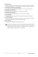
Quick Switches This motherboard has 2 quick buttons: power button and reset button. The power button and reset button allow users to quickly turn on/off or reset the computer in an open-case environment when they want to change hardware components or conduct hardware testing. PW_SW: Power switch RST_SW: Reset switch PHASE LED The number of lighted LEDs indicates the CPU loading. The higher the CPU loading, the more the number of lighted LEDs. To enable the Phase LED display function, please first enable Dynamic Energy Saver 2. Refer to Chapter 4, "Dynamic Energy Saver 2," for more details. NB PHASE LED The number of lighted LEDs indicates the North Bridge loading. The higher the North Bridge loading, the more the number of lighted LEDs. - 23 - Hardware Installation
-
 1
1 -
2
-
3
-
4
-
5
-
6
-
7
-
8
-
9
-
10
-
11
-
12
-
13
-
14
-
15
-
16
-
17
-
 18
18 -
 19
19 -
 20
20 -
 21
21 -
 22
22 -
 23
23 -
 24
24 -
 25
25 -
 26
26 -
 27
27 -
 28
28 -
29
-
30
-
31
-
32
-
33
-
34
-
35
-
36
-
37
-
38
-
39
-
40
-
41
-
42
-
43
-
44
-
45
-
46
-
47
-
48
-
49
-
50
-
51
-
52
-
53
-
54
-
55
-
56
-
57
-
58
-
59
-
60
-
61
-
62
-
63
-
64
-
65
-
66
-
67
-
68
-
69
-
70
-
71
-
72
-
73
-
74
-
75
-
76
-
77
-
78
-
79
-
80
-
81
-
82
-
83
-
84
-
85
-
86
-
87
-
88
-
89
-
90
-
91
-
92
-
93
-
94
-
95
-
96
-
97
-
98
-
99
-
100
-
101
-
102
-
103
-
104
-
105
-
106
-
107
-
108
-
109
-
110
-
111
-
112
-
113
-
114
-
115
-
116
-
117
-
118
-
119
-
120
-
121
-
122
-
123
-
124
-
125
-
126
-
127
-
128
-
129
-
130
-
131
-
132
-
133
-
134
-
135
-
136
-
137
-
138
-
139
-
140
-
141
-
142
-
143
-
144
 |
 |
