Gigabyte GA-Z270M-D3H Users Manual - Page 15
Installation Notices for the M.2, and SATA Connectors, F_PANEL Front Panel Header, SPEAK, PLED/PWR_LED
 |
View all Gigabyte GA-Z270M-D3H manuals
Add to My Manuals
Save this manual to your list of manuals |
Page 15 highlights
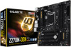
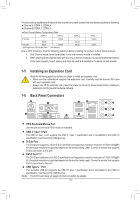
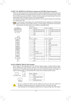
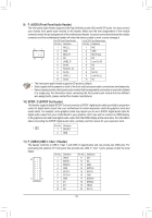
Installation Notices for the M.2, and SATA Connectors: Due to the limited number of lanes provided by the Chipset, the availability of the SATA connectors may be affected by the type of devices installed in the M2_32G connector. The M2_32G connector shares bandwidth with the SATA3 0 connector. Refer to the following table for details. Type of M.2 SSD Connector SATA3 0 SATA3 1 SATA3 2 SATA3 3 SATA3 4 SATA3 5 M.2 SATA SSD r a a a a a M.2 PCIe x4 SSD a a a a a a M.2 PCIe x2 SSD a a a a a a No M.2 SSD Installed a a a a a a a: Available r: Not available 8) F_PANEL (Front Panel Header) Connect the power switch, reset switch, speaker, chassis intrusion switch/sensor and system status indicator on the chassis to this header according to the pin assignments below. Note the positive and negative pins before connecting the cables. Power LED Power Switch Speaker •• PLED/PWR_LED (Power LED, Yellow/Purple): PLED+ PLED- PW+ PWSPEAK+ NC NC SPEAK- 2 20 1 19 HD+ HD- RESRES+ CICI+ PWR_LED+ PWR_LEDPWR_LED- Hard Drive Reset Activity LED Switch Power LED Chassis Intrusion Header System Status LED S0 On S3/S4/S5 Off Connects to the power status indicator on the chassis front panel. The LED is on when the system is operating. The LED is off when the system is in S3/S4 sleep state or powered off (S5). •• PW (Power Switch, Red): Connects to the power switch on the chassis front panel. You may configure the way to turn off your system using the power switch (refer to Chapter 2, "BIOS Setup," "Power," for more information). •• SPEAK (Speaker, Orange): Connects to the speaker on the chassis front panel. The system reports system startup status by issuing a beep code. One single short beep will be heard if no problem is detected at system startup. •• HD (Hard Drive Activity LED, Blue): Connects to the hard drive activity LED on the chassis front panel. The LED is on when the hard drive is reading or writing data. •• RES (Reset Switch, Green): Connects to the reset switch on the chassis front panel. Press the reset switch to restart the computer if the computer freezes and fails to perform a normal restart. •• CI (Chassis Intrusion Header, Gray): Connects to the chassis intrusion switch/sensor on the chassis that can detect if the chassis cover has been removed. This function requires a chassis with a chassis intrusion switch/sensor. •• NC (Orange): No Connection. The front panel design may differ by chassis. A front panel module mainly consists of power switch, reset switch, power LED, hard drive activity LED, speaker and etc. When connecting your chassis front panel module to this header, make sure the wire assignments and the pin assignments are matched correctly. - 15 -
-
 1
1 -
2
-
3
-
4
-
5
-
6
-
7
-
8
-
9
-
 10
10 -
 11
11 -
 12
12 -
 13
13 -
 14
14 -
 15
15 -
 16
16 -
 17
17 -
 18
18 -
 19
19 -
 20
20 -
21
-
22
-
23
-
24
-
25
-
26
-
27
-
28
-
29
-
30
-
31
-
32
-
33
-
34
-
35
-
36
-
37
-
38
-
39
-
40
-
41
-
42
-
43
-
44
 |
 |
