Gigabyte GA-Z68A-D3H-B3 Manual
Gigabyte GA-Z68A-D3H-B3 Manual
 |
UPC - 818313013149
View all Gigabyte GA-Z68A-D3H-B3 manuals
Add to My Manuals
Save this manual to your list of manuals |
Gigabyte GA-Z68A-D3H-B3 manual content summary:
- Gigabyte GA-Z68A-D3H-B3 | Manual - Page 1
GA-Z68A-D3H-B3 User's Manual Rev. 1001 12ME-Z68D3HB-1001R - Gigabyte GA-Z68A-D3H-B3 | Manual - Page 2
Motherboard GA-Z68A-D3H-B3 Apr. 29, 2011 Motherboard GA-Z68A-D3H-B3 Apr. 29, 2011 - Gigabyte GA-Z68A-D3H-B3 | Manual - Page 3
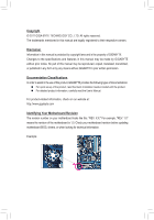
at: http://www.gigabyte.com Identifying Your Motherboard Revision The revision number on your motherboard looks like this: "REV: X.X." For example, "REV: 1.0" means the revision of the motherboard is 1.0. Check your motherboard revision before updating motherboard BIOS, drivers, or when looking - Gigabyte GA-Z68A-D3H-B3 | Manual - Page 4
-B3 Motherboard Layout 7 GA-Z68A-D3H-B3 Motherboard Block Diagram 8 Chapter 1 Hardware Installation 9 1-1 Installation Precautions 9 1-2 Product Specifications 10 1-3 Installing the CPU and CPU Cooler 13 1-3-1 Installing the CPU 13 1-3-2 Installing the CPU Cooler 15 1-4 Installing the Memory - Gigabyte GA-Z68A-D3H-B3 | Manual - Page 5
57 3-1 Installing Chipset Drivers 57 3-2 Application Software 58 3-3 Technical Manuals 58 3-4 Contact...59 3-5 System...59 3-6 Download Center 60 3-7 New Utilities...60 Chapter 4 Unique Features 61 4-1 Xpress Recovery2 61 4-2 BIOS Update Utilities 64 4-2-1 Updating the BIOS with the Q-Flash - Gigabyte GA-Z68A-D3H-B3 | Manual - Page 6
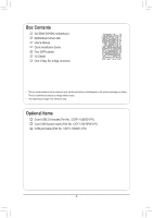
Box Contents GA-Z68A-D3H-B3 motherboard Motherboard driver disk User's Manual Quick Installation Guide Four SATA cables I/O Shield One 2-Way SLI bridge connector • The box contents above are for reference only and the actual items shall depend on the product package you obtain. The box contents are - Gigabyte GA-Z68A-D3H-B3 | Manual - Page 7
OPTICAL CPU_FAN LGA1155 PWR_FAN ATX R_USB30 USB_LAN AUDIO Etron EJ168 PCIEX1_1 Realtek RTL8111E PCIEX16 PCIEX1_2 CODEC PCIEX4 PCIEX8 PCI1 iTE IT8728 PCI2 F_AUDIO COMA SPDIF_O GA-Z68A-D3H-B3 BAT DDR3_4 DDR3_2 DDR3_3 DDR3_1 Intel® Z68 B_BIOS M_BIOS PCIe to PCI Bridge SATA3_0 SATA3_1 - Gigabyte GA-Z68A-D3H-B3 | Manual - Page 8
GA-Z68A-D3H-B3 Motherboard Block Diagram PCIe CLK (100 MHz) 1 PCI Express x16 or 2 PCI Express x8 LGA1155 CPU CPU CLK+/- (100 MHz) DDR3 2133/1866/1600/1333/1066 MHz Dual Channel Memory x16 x8 Switch PCI Express Bus DMI Interface 1 PCI Express x4 2 PCI Express x1 LAN or RJ45 x4 x1 Switch - Gigabyte GA-Z68A-D3H-B3 | Manual - Page 9
's manual and follow these procedures: •• Prior to installation, do not remove or break motherboard strap when handling electronic com- ponents such as a motherboard, CPU or memory. If you do not have an ESD wrist strap steps or have a problem related to the use of the product, please consult - Gigabyte GA-Z68A-D3H-B3 | Manual - Page 10
i3 processors/Intel® Pentium® processors/Intel® Celeron® processors in the LGA1155 package (Go to GIGABYTE's website for the latest CPU support list.) ŠŠ L3 cache varies with CPU Chipset ŠŠ Intel® Z68 Express Chipset Memory Onboard Graphics Audio ŠŠ 4 x 1.5V DDR3 DIMM sockets supporting up to - Gigabyte GA-Z68A-D3H-B3 | Manual - Page 11
x SATA 3Gb/s connectors ŠŠ 1 x CPU fan header ŠŠ 2 x system fan headers ŠŠ 1 x power fan header ŠŠ 1 x front panel header ŠŠ 1 x front panel audio header ŠŠ 1 x S/PDIF Out header ŠŠ 4 x USB 2.0/1.1 headers ŠŠ 1 x serial port header ŠŠ 1 x clearing CMOS jumper ŠŠ 1 x Trusted Platform Module - Gigabyte GA-Z68A-D3H-B3 | Manual - Page 12
Features ŠŠ Support for @BIOS ŠŠ Support for Q-Flash ŠŠ Support for Xpress BIOS Rescue ŠŠ Support for Download Center ŠŠ Support for Xpress Install ŠŠ Support for Xpress Recovery2 ŠŠ Support for EasyTune * Available functions in EasyTune may differ by motherboard model. ŠŠ Support for - Gigabyte GA-Z68A-D3H-B3 | Manual - Page 13
specifications including the CPU, graphics card, memory, hard drive, etc. 1-3-1 Installing the CPU A. Locate the alignment keys on the motherboard CPU socket and the notches on the CPU. LGA1155 CPU Socket Alignment Key Alignment Key Pin One Corner of the CPU Socket LGA1155 CPU Notch Notch - Gigabyte GA-Z68A-D3H-B3 | Manual - Page 14
B. Follow the steps below to correctly install the CPU into the motherboard CPU socket. Before installing the CPU, make sure to turn off the computer and unplug the power cord from the power outlet to prevent damage to the CPU. Step 1: Gently press the CPU socket lever handle down and away from the - Gigabyte GA-Z68A-D3H-B3 | Manual - Page 15
below to correctly install the CPU cooler on the motherboard. (The following procedure uses Intel® boxed cooler as the example (Refer to your CPU cooler installation manual for instructions on installing the cooler.) Step 5: After the installation, check the back of the motherboard. If the push - Gigabyte GA-Z68A-D3H-B3 | Manual - Page 16
. If you are unable to insert the memory, switch the direction. 1-4-1 Dual Channel Memory Configuration This motherboard provides four DDR3 memory sockets and supports Dual Channel Technology. After the memory is installed, the BIOS will automatically detect the specifications and capacity of - Gigabyte GA-Z68A-D3H-B3 | Manual - Page 17
DDR2 DIMMs are not compatible to each other or DDR DIMMs. Be sure to install DDR3 DIMMs on this motherboard. Notch DDR3 DIMM A DDR3 memory module has a notch, so it can only fit in one direction. Follow the steps below to correctly install your memory modules in the memory sockets. Step 1: Note the - Gigabyte GA-Z68A-D3H-B3 | Manual - Page 18
an expansion card: • Make sure the motherboard supports the expansion card. Carefully read the manual that came with your expansion card. • Always If necessary, go to BIOS Setup to make any required BIOS changes for your expansion card(s). 777 Install the driver provided with the expansion card - Gigabyte GA-Z68A-D3H-B3 | Manual - Page 19
/SLI-supported motherboard with two PCI Express x16 slots and correct driver - Two CrossFireX/SLI-ready graphics cards of identical brand and chip and correct driver - One CrossFire (Note)/SLI bridge connector - A power supply with sufficient power is recommended (Refer to the manual of - Gigabyte GA-Z68A-D3H-B3 | Manual - Page 20
AC3 and DTS require the use of an external decoder for decoding.) In Windows 7, select Start>Control Panel>Hardware and Sound>Sound>Playback, set Intel(R) Display Audio to the default playback device. (Note) The DVI-D port does not support D-Sub connection by adapter. Hardware Installation - 20 - - Gigabyte GA-Z68A-D3H-B3 | Manual - Page 21
the audio driver. Refer to the instructions on setting up a 2/4/5.1/7.1-channel audio configuration in Chapter 5, "Configuring 2/4/5.1/7.1-Channel Audio." • When removing the cable connected to a back panel connector, first remove the cable from your device and then remove it from the motherboard - Gigabyte GA-Z68A-D3H-B3 | Manual - Page 22
Connectors 1 3 5 2 6 7 8 14 10 9 11 13 15 4 12 4 12 1) ATX_12V 2) ATX 3) CPU_FAN 4) SYS_FAN1/2 5) PWR_FAN 6) BAT 7) SATA3_0/1 8) SATA2_2/3/4/5 9) F_PANEL 10) F_AUDIO 11) SPDIF_O 12 cable has been securely attached to the connector on the motherboard. Hardware Installation - 22 - - Gigabyte GA-Z68A-D3H-B3 | Manual - Page 23
ATX (2x2 12V Power Connector and 2x12 Main Power Connector) With the use of the power connector, the power supply can supply enough stable power to all the components on the motherboard . The 12V power connector mainly supplies power to the CPU. If the 12V power connector is not connected, the - Gigabyte GA-Z68A-D3H-B3 | Manual - Page 24
cable, be sure to connect it in the correct orientation (the black connector wire is the ground wire). The motherboard supports CPU fan speed control, which requires the use of a CPU fan with fan speed control design. For optimum heat dissipation, it is recommended that a system fan be installed - Gigabyte GA-Z68A-D3H-B3 | Manual - Page 25
conform to SATA 3Gb/s standard and are compatible with SATA 1.5Gb/s standard. Each SATA connector supports a single SATA device. The Intel Z68 Chipset supports RAID 0, RAID 1, RAID 5, and RAID 10. Refer to Chapter 5, "Configuring SATA Hard Drive(s)," for instructions on configur- ing a RAID array - Gigabyte GA-Z68A-D3H-B3 | Manual - Page 26
beep code. One single short beep will be heard if no problem is detected at system startup. If a problem is detected, the BIOS may issue beeps in different patterns to indicate the problem. Refer to Chapter 5, "Troubleshooting," for information about beep codes. •• HD (Hard Drive Activity LED, Blue - Gigabyte GA-Z68A-D3H-B3 | Manual - Page 27
7 NC 8 No Pin 8 No Pin 9 LINE2_L 9 Line Out (L) 10 GND 10 NC BIOS Switcher (X58A-OC) DB_POR••T The front panel audio header supports HD audio by default. If your chassis provides an AC'97 front panel audio module, refe1 r to the instructions on how to activate AC'97 functionality via the - Gigabyte GA-Z68A-D3H-B3 | Manual - Page 28
DY+ 7 GND 8 GND 9 No Pin 10 NC When the system is in S4/S5 mode, only the USB ports routed to the F_USB1 header can support the ON/OFF Charge function. •• Do not plug the IEEE 1394 bracket (2x5-pin) cable into the USB 2.0/1.1 header. •• Prior to installing the USB bracket - Gigabyte GA-Z68A-D3H-B3 | Manual - Page 29
After clearing the CMOS values and before turning on your computer, be sure to remove the jumper cap from the jumper. Failure to do so may cause damage to the motherboard. •• After system restart, go to BIOS Setup to load factory defaults (select Load Optimized De- faults) or manually configure - Gigabyte GA-Z68A-D3H-B3 | Manual - Page 30
Hardware Installation - 30 - - Gigabyte GA-Z68A-D3H-B3 | Manual - Page 31
the GIGABYTE Q-Flash or @BIOS utility. • Q-Flash allows the user to quickly and easily upgrade or back up BIOS without entering the operating system. • @BIOS is a Windows-based utility that searches and downloads the latest version of BIOS from the Internet and updates the BIOS. For instructions on - Gigabyte GA-Z68A-D3H-B3 | Manual - Page 32
) Function Keys B. The POST Screen Motherboard Model BIOS Version Award Modular BIOS v6.00PG Copyright (C) 1984-2011, Award Software, Inc. Z68A-D3H-B3 E15 . . . . : BIOS Setup : XpressRecovery2 : Boot Menu : Qflash 04/06/2011-Z68-7A89WG01C-00 Function Keys Function Keys - Gigabyte GA-Z68A-D3H-B3 | Manual - Page 33
User Password Save & Exit Setup Exit Without Saving ESC: Quit F8: Q-Flash Select Item F10: Save & Exit Setup Change CPU's Clock & Voltage F11: Save CMOS to BIOS F12: Load CMOS from BIOS BIOS Setup Program Function Keys Move the selection bar to select an item Execute - Gigabyte GA-Z68A-D3H-B3 | Manual - Page 34
CPU, memory, etc. Standard CMOS Features Use this menu to configure the system time and date, hard drive types, and the type of errors that stop the system boot, etc. Advanced BIOS the changes made in the BIOS Setup program to the CMOS and exit BIOS Setup. (Pressing can also carry out this - Gigabyte GA-Z68A-D3H-B3 | Manual - Page 35
on your overall system configurations. Incorrectly doing overclock/overvoltage may result in damage to CPU, chipset, or memory and reduce the useful life of these to boot. If this occurs, clear the CMOS values and reset the board to default values.) CMOS Setup Utility-Copyright (C) 1984-2011 Award - Gigabyte GA-Z68A-D3H-B3 | Manual - Page 36
: Auto) (Note 1) This item is present only when you install a memory module that supports this feature. (Note 2) This item is present only when you install a CPU that supports this feature. For more information about Intel CPUs' unique features, please visit Intel's website. BIOS Setup - 36 - - Gigabyte GA-Z68A-D3H-B3 | Manual - Page 37
this item to Disabled if you want to manually configure CPU Turbo ratios in BIOS setup. (Default: Disabled) Intel(R) Turbo Boost Tech. (Note) Allows you to determine whether to enable the Intel CPU Turbo Boost technology. Auto lets the BIOS automatically configure this setting. (Default: Auto) Turbo - Gigabyte GA-Z68A-D3H-B3 | Manual - Page 38
your system fails to boot after overclocking, please wait for 20 seconds to allow for automated system reboot, or clear the CMOS values to reset the board to default values. (Default: Disabled) BCLK/DMI/PEG Frequency(0.1MHz) Allows you to manually set the CPU base clock and DMI/PCIe bus frequency - Gigabyte GA-Z68A-D3H-B3 | Manual - Page 39
Enabled allows the system to simultaneously access different ranks of the memory to increase memory performance and stability. Auto lets the BIOS automatically configure this setting. (Default: Auto) (Note) This item is present only when you install a memory module that supports this feature. - 39 - Gigabyte GA-Z68A-D3H-B3 | Manual - Page 40
>>>>> Channel A/B Timing Settings CMOS Setup Utility-Copyright (C) 1984-2011 Award Software Channel A Timing Move Enter: Select F5: Previous Values +/-/PU/PD: Value F10: Save F6: Fail-Safe Defaults ESC: Exit F1: General Help tFAW Options are: Auto (default), 1~63. BIOS Setup - 40 - - Gigabyte GA-Z68A-D3H-B3 | Manual - Page 41
Advanced Voltage Settings CMOS Setup Utility-Copyright F10: Save F6: Fail-Safe Defaults ESC: Exit F1: General Help F7: Optimized Defaults >>> CPU CPU voltage more constant under light and heavy CPU load. (Default: Auto) Standard Disables Load-Line Calibration and sets VDroop following Intel - Gigabyte GA-Z68A-D3H-B3 | Manual - Page 42
/PD: Value F10: Save F6: Fail-Safe Defaults ESC: Exit F1: General Help F7: Optimized Defaults Isochronous Support Determines whether to enable specific streams within the CPU and Chipset. (Default: Enabled) Virtualization Technology (Note) Enables or disables Intel Virtualization Technology - Gigabyte GA-Z68A-D3H-B3 | Manual - Page 43
-2011 Award Software Standard CMOS Features Date (mm:dd Base Memory Extended Memory Total Memory 640K 1022M 1024M Move Enter: Select F5: Previous Values +/-/PU/PD: Value F10: Save BIOS automatically detect SATA devices during the POST. (Default) • Manual Allows you to manually - Gigabyte GA-Z68A-D3H-B3 | Manual - Page 44
system boot will not stop for a keyboard error but stop for all other errors. (Default) Memory These fields are read-only and are determined by the BIOS POST. Base Memory Also called conventional memory. Typically, 640 KB will be reserved for the MS-DOS operating system. Extended - Gigabyte GA-Z68A-D3H-B3 | Manual - Page 45
: Value F10: Save down on the list. Press BIOS Setup program. (Default) System A password is required for booting the system and for entering the BIOS Setup program. (Note) This item is present only when you install a CPU that supports this feature. For more information about Intel - Gigabyte GA-Z68A-D3H-B3 | Manual - Page 46
use only this memory for display. Options are: 32MB+2MB for GTT~ 480MB+2MB for GTT. (Default: 64MB+2MB for GTT) (Note) This item is present only when you install a CPU that supports this feature. For more information about Intel CPUs' unique features, please visit Intel's website. BIOS Setup - 46 - Gigabyte GA-Z68A-D3H-B3 | Manual - Page 47
driver to enable advanced Serial ATA features such as Native Command Queuing and hot plug. SATA Port0-3 Native Mode (Intel Z68 Chipset) to Disabled if you wish to install operating systems that do not support Native mode. Enabled Allows the SATA controllers to operate in Native IDE - Gigabyte GA-Z68A-D3H-B3 | Manual - Page 48
Intel RAID ROM messages during the POST when the Intel SATA RAID function is enabled. (Default: Enabled) Azalia Codec Enables or disables the onboard audio F10: Save F6: Fail-Safe Defaults ESC: Exit F1: General Help F7: Optimized Defaults This motherboard If no cable problem is detected on the - Gigabyte GA-Z68A-D3H-B3 | Manual - Page 49
When a Cable Problem Occurs... If a cable problem occurs on a specified pair of wires, the Status field will show Short and then length shown will be the base I/O address and corresponding interrupt. Options are: Auto, 3F8/IRQ4 (default), 2F8/IRQ3, 3E8/IRQ4, 2E8/IRQ3, Disabled. - 49 - BIOS Setup - Gigabyte GA-Z68A-D3H-B3 | Manual - Page 50
Select F5: Previous Values +/-/PU/PD: Value F10: Save F6: Fail-Safe Defaults ESC: Exit : To use this function, you need an ATX power supply providing at least 1A on the supports wake-up function. (Default: Enabled) (Note) Supported on Windows 7/Vista operating system only. BIOS Setup - 50 - - Gigabyte GA-Z68A-D3H-B3 | Manual - Page 51
HPET Support ( the HPET Support is set you need an ATX power supply you need an ATX power supply providing at password to clear the password Memory The system returns to its last known awake state upon the return of the AC power. ErP Support Supported on Windows 7/Vista operating system only. - 51 - Gigabyte GA-Z68A-D3H-B3 | Manual - Page 52
detection device attached to the motherboard CI header. If the system chassis cover is removed, this field will show "Yes", otherwise it will show "No". To clear the chassis intrusion status record, set Reset Case Open Status to Enabled, save the settings to the CMOS, and then restart your system - Gigabyte GA-Z68A-D3H-B3 | Manual - Page 53
FAN Control is set to Manual. Options are: 0.75 PWM value /oC ~ 2.50 PWM value /oC. CPU Smart FAN Mode Specifies how to control CPU fan speed. This item is configurable only when CPU Smart FAN Control is enabled. Auto Lets the BIOS automatically detect the type of CPU fan installed and sets the - Gigabyte GA-Z68A-D3H-B3 | Manual - Page 54
: Save CMOS to BIOS F12: Load CMOS from BIOS Press on this item and then press the key to load the optimal BIOS default settings. The BIOS defaults settings help the system to operate in optimum state. Always load the Optimized defaults after updating the BIOS or after clearing the CMOS - Gigabyte GA-Z68A-D3H-B3 | Manual - Page 55
F8: Q-Flash Select Item F10: Save & Exit Setup Change/Set/Disable Password F11: Save CMOS to BIOS F12: Load CMOS from BIOS Press on this to make changes to BIOS settings. The user password only allows you to view the BIOS settings but not to make changes. To clear the password, press < - Gigabyte GA-Z68A-D3H-B3 | Manual - Page 56
Power Management Setup Save & Exit Setup PC Health Status Exit Without Saving ESC: Quit F8: Q-Flash Select Item F10: Save & Exit Setup Save Data to CMOS F11: Save CMOS to BIOS F12: Load CMOS from BIOS Press on this item and press the key. This saves the changes to the - Gigabyte GA-Z68A-D3H-B3 | Manual - Page 57
install new GIGABYTE utilities. Click Yes to automatically install the utilities. Or click No if you want to manually select the utilities to install on the Application Software page later. • For USB 2.0 driver support under the Windows XP operating system, please install the Windows XP Service Pack - Gigabyte GA-Z68A-D3H-B3 | Manual - Page 58
applications that GIGABYTE develops and some free software. You can click the Install button on the right of an item to install it. 3-3 Technical Manuals This page provides GIGABYTE's application guides, content descriptions for this driver disk, and the motherboard manuals. Drivers Installation - Gigabyte GA-Z68A-D3H-B3 | Manual - Page 59
3-4 Contact For the detailed contact information of the GIGABYTE Taiwan headquarter or worldwide branch offices, click the URL on this page to link to the GIGABYTE website. 3-5 System This page provides the basic system information. - 59 - Drivers Installation - Gigabyte GA-Z68A-D3H-B3 | Manual - Page 60
Center To update the BIOS, drivers, or applications, click the Download Center button to link to the GIGABYTE website. The latest version of the BIOS, drivers, or applications will be displayed. 3-7 New Utilities This page provides a quick link to GIGABYTE's lately developed utilities for users - Gigabyte GA-Z68A-D3H-B3 | Manual - Page 61
of it. Supporting NTFS, FAT32, drivers are installed. • The amount of data and hard drive access speed may affect the speed at which the data is backed up/ restored. • It takes longer to back up a hard drive than to restore it. System Requirements: • At least 512 MB of system memory • VESA compatible - Gigabyte GA-Z68A-D3H-B3 | Manual - Page 62
note that if there is no enough unallocated space, Xpress Recovery2 cannot save the backup file. B. Accessing Xpress Recovery2 1. Boot from the motherboard driver disk to access Xpress Recovery2 for the first time. When you see the following message: Press any key to startup Xpress Recovery2, press - Gigabyte GA-Z68A-D3H-B3 | Manual - Page 63
D. Using the Restore Function in Xpress Recovery2 Select RESTORE to restore the backup to your hard drive in case the system breaks down. The RESTORE option will not be present if no backup is created before. E. Removing the Backup Step 1: If you wish to remove the backup file, select REMOVE. Step - Gigabyte GA-Z68A-D3H-B3 | Manual - Page 64
, if the BIOS update file is saved to a hard drive in RAID/AHCI mode or a hard drive attached to an independent SATA controller, use the key during the POST to access Q-Flash. Award Modular BIOS v6.00PG Copyright (C) 1984-2011, Award Software, Inc. Z68A-D3H-B3 E15 . . . . : BIOS Setup - Gigabyte GA-Z68A-D3H-B3 | Manual - Page 65
HDD 1-0 Loa d CMO S Default Enable Update BIOS from Drive Save BIOS to Drive Enter : Run hi:Move Total size : 0 ESC:Reset Free size : 0 F10:Power Off 3. Select the BIOS update file and press . Make sure the BIOS update file matches your motherboard model. Step - Gigabyte GA-Z68A-D3H-B3 | Manual - Page 66
load BIOS defaults. System will re-detect all peripheral devices after a BIOS update, so we recommend that you reload BIOS defaults. CMOS Flash Select Item F10: Save & Exit Setup Load Optimized Defaults F11: Save CMOS to BIOS F12: Load CMOS from BIOS Press to load BIOS defaults Step 6: - Gigabyte GA-Z68A-D3H-B3 | Manual - Page 67
. If the BIOS update file for your motherboard is not present on the @BIOS server site, please manually download the BIOS update file from GIGABYTE's website and follow the instructions in "Update the BIOS without Using the Internet Update Function" below. 2. Update the BIOS without Using the - Gigabyte GA-Z68A-D3H-B3 | Manual - Page 68
in EasyTune 6 may differ by motherboard model. Grayed-out area(s) indicates that the item is not configurable or the function is not supported. Incorrectly doing overclock/overvoltage may result in damage to the hardware components such as CPU, chipset, and memory and reduce the useful life of - Gigabyte GA-Z68A-D3H-B3 | Manual - Page 69
for using Q-Share After installing Q-Share from the motherboard driver disk, go to Start>All Programs>GIGABYTE>Q-Share. exe to launch the Q-Share tool. shared data folder Changes the data folder to be shared (Note) Updates Q-Share online Displays the current Q-Share version Exits Q-Share ( - Gigabyte GA-Z68A-D3H-B3 | Manual - Page 70
the three levels of CPU performance enhancement, and SMART QuickBoost automatically adjusts CPU performance. Instructions: Select a CPU performance boost level and restart your computer for the changes to take effect. Whether SMART QuickBoost is supported depends on the motherboard model. Unique - Gigabyte GA-Z68A-D3H-B3 | Manual - Page 71
your files from the backup image System Recovery... Allows you to recover your system from the backup image • Supported operating systems: Windows 7 and Vista. • Smart Recovery 2 only supports NTFS file system. • You need to select the destination partition in Settings the first time you use Smart - Gigabyte GA-Z68A-D3H-B3 | Manual - Page 72
, and remind users of the dates. It also stores the recorded data in the main and backup BIOS simultaneously, which can prevent loss of the data in case the system/hard drive fails. Instructions: Enter the Smart 6™ password to launch the SMART DualBIOS utility. You can record personal passwords and - Gigabyte GA-Z68A-D3H-B3 | Manual - Page 73
were moved within the hard drive or copied to an external storage device (Note 2). Instructions: Select the Enable check box at the bottom of the ON/OFF Recorder or File the User Password in the system BIOS Setup program to prevent the system time being changed by other users. - 73 - Unique - Gigabyte GA-Z68A-D3H-B3 | Manual - Page 74
your Bluetooth cell phone, click Refresh to let Auto Green re-detect the device.) Before creating a Bluetooth cell phone key, make sure your motherboard has a Bluetooth receiver and you have turned on the search and Bluetooth functions on your phone. Configuring the Bluetooth cell phone key: After - Gigabyte GA-Z68A-D3H-B3 | Manual - Page 75
motherboard drivers, including the X.H.D utility. Or you can go to the Application Software screen to individually install the X.H.D utility later. B. Using GIGABYTE eXtreme Hard Drive (X.H.D) Instructions X.H.D utility only supports the SATA controllers integrated in the Intel Chipset. (Note 2) It - Gigabyte GA-Z68A-D3H-B3 | Manual - Page 76
, CPU VCore and system temperature. • Control (System Status Control): The Control tab allows for controlling system power states with restart, power off, suspend, and hibernate options. (Note 1) (Note 2) (Note 3) Supported on Windows 7, Vista, and XP. For Windows XP, be sure to update Internet - Gigabyte GA-Z68A-D3H-B3 | Manual - Page 77
Configure SATA controller mode in BIOS Setup. C. Configure a RAID array in RAID BIOS. (Note 1) D. Install the SATA RAID/AHCI driver (Note 2) and operating on this motherboard, the SATA3_0, SATA3_1 (Note 3), SATA2_2, SATA2_3, SATA2_4 and SATA2_5 ports are supported by the Z68 Chipset.) Then connect - Gigabyte GA-Z68A-D3H-B3 | Manual - Page 78
+/-/PU/PD: Value F10: Save F6: Fail-Safe Defaults Figure 1 ESC: Exit F1: General Help F7: Optimized Defaults Step 2: Save changes and exit BIOS Setup. The BIOS Setup menus described in this section may differ from the exact settings for your motherboard. The actual BIOS Setup menu options - Gigabyte GA-Z68A-D3H-B3 | Manual - Page 79
BIOS Enter the RAID BIOS setup utility to configure a RAID array. Skip this step and proceed with the installation of Windows operating system for a non-RAID configuration. Step 1: After the POST memory Intel(R) Rapid Storage Technology - Option ROM - 10.1.0.1008 Copyright(C) 2003-10 Intel - Gigabyte GA-Z68A-D3H-B3 | Manual - Page 80
press . Then, select a RAID level (Figure 4). RAID levels supported include RAID 0, RAID 1, Recovery, RAID 10, and RAID 5 (the stripe block size, press . Intel(R) Rapid Storage Technology - Option ROM - 10.1.0.1008 Copyright(C) 2003-10 Intel Corporation. All Rights Reserved. [ CREATE - Gigabyte GA-Z68A-D3H-B3 | Manual - Page 81
Figure 6). Intel(R) Rapid Storage Technology - Option ROM - 10.1.0.1008 Copyright(C) 2003-10 Intel Corporation. Figure 7) Intel(R) Rapid Storage Technology - Option ROM - 10.1.0.1008 Copyright(C) 2003-10 Intel Corporation. Select Menu To exit the RAID BIOS utility, press or select 5. Exit in - Gigabyte GA-Z68A-D3H-B3 | Manual - Page 82
drive is hidden. Step 1: Select Create RAID Volume in MAIN MENU and press (Figure 8). Intel(R) Rapid Storage Technology - Option ROM - 10.1.0.1008 Copyright(C) 2003-10 Intel Corporation. All Rights Reserved. [ MAIN MENU ] 1. Create RAID Volume 2. Delete RAID Volume 5. Exit 3. Reset Disks - Gigabyte GA-Z68A-D3H-B3 | Manual - Page 83
10) Intel(R) Rapid Storage Technology - Option ROM - 10.1.0.1008 Copyright(C) 2003-10 Intel Corporation. to update data from the master drive to the recovery drive manually using the Intel : On Request: volume is updated manually Continuous: volume is updated automatically [hi]-Change [TAB]- - Gigabyte GA-Z68A-D3H-B3 | Manual - Page 84
>. When prompted to confirm your selection (Figure 12), press to confirm or to abort. Intel(R) Rapid Storage Technology - Option ROM - 10.1.0.1008 Copyright(C) 2003-10 Intel Corporation. All Rights Reserved. Name Volume0 Level RAID0(Stripe) [ DELETE VOLUME MENU ] Drives 2 Capacity - Gigabyte GA-Z68A-D3H-B3 | Manual - Page 85
, the hard drive(s) may not be recognized during the Windows setup process. First, copy the driver from the motherboard driver disk to a floppy disk. Refer to the methods below. Method A: • For the Intel Z68, copy all files in the \BootDrv\iRST\32Bit folder to your floppy disk. To install Windows - Gigabyte GA-Z68A-D3H-B3 | Manual - Page 86
support disk provided by an adapter manufacturer. Select the SCSI Adapter you want from the following list, or press ESC to return to the previous screen. Intel(R) ICH7R/DH SATA RAID Controller Intel(R) ICH7MDH SATA RAID Controller Intel(R) Desktop/Workstation/Server Express Chipset SATA - Gigabyte GA-Z68A-D3H-B3 | Manual - Page 87
enable automatic rebuild on this stage, you have to manually rebuild the array in the operating system (see the next page for more details). Intel(R) Rapid Storage Technology - Option ROM - 10.1.0.1008 Copyright(C) 2003-10 Intel Corporation. All Rights Reserved. [ MAIN MENU ] 1. Create RAID Volume - Gigabyte GA-Z68A-D3H-B3 | Manual - Page 88
• Performing the Rebuild in the Operating System While in the operating system, make sure the chipset driver has been installed from the motherboard driver disk. Then launch the Intel Rapid Storage Technology utility from All Programs in the Start menu. Step 1: Go to the Manage menu and click - Gigabyte GA-Z68A-D3H-B3 | Manual - Page 89
Recovery Volume only) When two hard drives are set to Recovery Volume in Update on Request mode, you can restore the master drive data to the last instructions to complete and exit the RAID Configuration Utility. Intel(R) Rapid Storage Technology - Option ROM - 10.1.0.1008 Copyright(C) 2003-10 Intel - Gigabyte GA-Z68A-D3H-B3 | Manual - Page 90
jack and manually configure the jack for microphone functionality. • Audio signals will be present on both of the front and back panel audio connections simultaneously. If you want to mute the back panel audio (only supported when using an HD front panel audio module), refer to instructions on page - Gigabyte GA-Z68A-D3H-B3 | Manual - Page 91
tab. In the Speaker Configuration list, select Stereo, Quadraphonic, 5.1 Speaker, or 7.1 Speaker according to the type of speaker configuration you wish to set up. Then the speaker setup is completed. B. Configuring Sound Effect You may configure an audio environment on the Sound Effects tab - Gigabyte GA-Z68A-D3H-B3 | Manual - Page 92
the Connector Settings dialog box, select the Disable front panel jack detection check box. Click OK to complete. D. Muting the Back Panel Audio (For HD Audio Only) Click Device advanced settings on the top right corner on the Speaker Configuration tab to open the Device advanced settings dialog box - Gigabyte GA-Z68A-D3H-B3 | Manual - Page 93
Connect a S/PDIF optical cable to the corresponding S/PDIF out connector as shown below and an external decoder for transmitting the S/PDIF digital audio signals. Connects to a S/PDIF optical cable 2. Configuring S/PDIF Out: On the Digital Output(Optical) screen , (Note) click the Default Format tab - Gigabyte GA-Z68A-D3H-B3 | Manual - Page 94
5-2-3 Configuring Microphone Recording Step 1: After installing the audio driver, the HD Audio Manager icon will appear in the notification area. Double-click the icon to access the HD Audio Manager. Step 2: Connect your microphone to the Mic in jack (pink) on the back panel or the Mic in jack ( - Gigabyte GA-Z68A-D3H-B3 | Manual - Page 95
, click Start, point to All Programs, point to Accessories, and then click Sound Recorder to begin the sound recording. * Enabling Stereo Mix If the HD Audio Manager does not display the recording device you wish to use, refer to the steps below. The following steps explain how to enable Stereo Mix - Gigabyte GA-Z68A-D3H-B3 | Manual - Page 96
the Start Recording button . 3. To stop recording audio, click the Stop Recording button . Be sure to save the recorded audio file upon completion. B. Playing the Recorded Sound You can play your recording in a digital media player program that supports your audio file format. Appendix - 96 - - Gigabyte GA-Z68A-D3H-B3 | Manual - Page 97
driver from the motherboard driver disk or download the audio driver from GIGABYTE's website to install. For more details, go to the Support & Downloads\FAQ page on our website and search for "onboard HD audio driver." Q: What do the beeps emitted during the POST mean? A: The following Award BIOS - Gigabyte GA-Z68A-D3H-B3 | Manual - Page 98
the CPU cooler power cable to the motherboard. Yes The problem is verified and solved. Check if the memory is installed properly on the memory slot. No Correctly insert the memory into the memory socket. Yes The problem is verified and solved. Insert the graphics card. Connect the ATX - Gigabyte GA-Z68A-D3H-B3 | Manual - Page 99
verified and solved. END If the procedure above is unable to solve your problem, contact the place of purchase or local dealer for help. Or go to the Support & Downloads\Technical Support page to submit your question. Our customer service staff will reply you as soon as possible. - 99 - Appendix - Gigabyte GA-Z68A-D3H-B3 | Manual - Page 100
Appendix - 100 - - Gigabyte GA-Z68A-D3H-B3 | Manual - Page 101
- 101 - Appendix - Gigabyte GA-Z68A-D3H-B3 | Manual - Page 102
Appendix - 102 - - Gigabyte GA-Z68A-D3H-B3 | Manual - Page 103
City 231,Taiwan TEL: +886-2-8912-4000 FAX: +886-2-8912-4003 Tech. and Non-Tech. Support (Sales/Marketing) : http://ggts.gigabyte.com.tw WEB address (English): http://www.gigabyte.com WEB address (Chinese): http://www.gigabyte.tw • G.B.T. INC. - U.S.A. TEL: +1-626-854-9338 FAX: +1-626-854-9339 Tech - Gigabyte GA-Z68A-D3H-B3 | Manual - Page 104
.com.ro • Serbia WEB address : http://www.gigabyte.co.rs • Kazakhstan WEB address : http://www.gigabyte.kz You may go to the GIGABYTE website, select your language in the language list on the top right corner of the website. • GIGABYTE Global Service System To submit a technical or non-technical
-
 1
1 -
 2
2 -
 3
3 -
 4
4 -
 5
5 -
 6
6 -
 7
7 -
8
-
9
-
10
-
11
-
12
-
13
-
14
-
15
-
16
-
17
-
18
-
19
-
20
-
21
-
22
-
23
-
24
-
25
-
26
-
27
-
28
-
29
-
30
-
31
-
32
-
33
-
34
-
35
-
36
-
37
-
38
-
39
-
40
-
41
-
42
-
43
-
44
-
45
-
46
-
47
-
48
-
49
-
50
-
51
-
52
-
53
-
54
-
55
-
56
-
57
-
58
-
59
-
60
-
61
-
62
-
63
-
64
-
65
-
66
-
67
-
68
-
69
-
70
-
71
-
72
-
73
-
74
-
75
-
76
-
77
-
78
-
79
-
80
-
81
-
82
-
83
-
84
-
85
-
86
-
87
-
88
-
89
-
90
-
91
-
92
-
93
-
94
-
95
-
96
-
97
-
98
-
99
-
100
-
101
-
102
-
103
-
104
 |
 |

GA-Z68A-D3H-B3
User's Manual
Rev. 1001
12ME-Z68D3HB-1001R