Gigabyte GA-Z68X-UD3P-B3 Manual - Page 31
TPM Trusted Platform Module Header, PHASE LED, Refer to Dynamic Energy Saver
 |
UPC - 818313012678
View all Gigabyte GA-Z68X-UD3P-B3 manuals
Add to My Manuals
Save this manual to your list of manuals |
Page 31 highlights
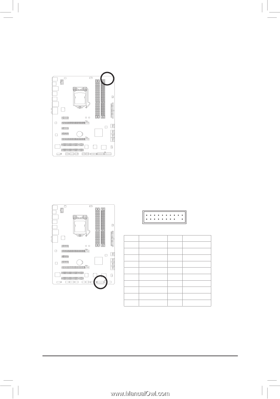
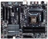
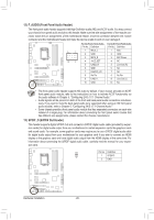
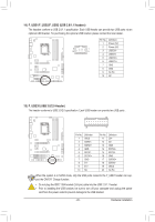
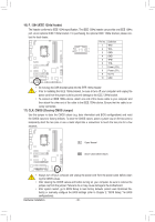
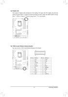
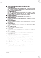
18) PHASE LED The number of lighted LEDs indicates the CPU loading. The higher the CPU loading, the more the number of lighted LEDs. To enable the Phase LED display function, please first enable Dynamic Energy Saver™ 2. Refer to Chapter 4, "Dynamic Energy Saver™ 2," for more details. F_USB30 F_AUDIO(H) 1 19) TPM (Trusted Platform Module Header) You may connect a TPM (Trusted Platform Module) to this header. DB_PORT BIOS Switc 1 1 19 TPM w/housing 20 Pin No. 1 2 3 4 5 6 7 8 9 10 Definition LCLK GND LFRAME No Pin LRESET NC LAD3 LAD2 VCC3 LAD1 1 Voltage measurement module(X58A-OC) PWM Swi DIP 2 DIP Pin No. Definition 1 23 11 LAD0 12 GND PCIe power connector (SATA)(X58A-OC) 13 NC 14 ID 15 SB3V 16 SERIRQ 17 GND 18 NC 19 NC 20 SUSCLK - 31 - Hardware Installation
-
 1
1 -
2
-
3
-
4
-
5
-
6
-
7
-
8
-
9
-
10
-
11
-
12
-
13
-
14
-
15
-
16
-
17
-
18
-
19
-
20
-
21
-
22
-
23
-
24
-
25
-
 26
26 -
 27
27 -
 28
28 -
 29
29 -
 30
30 -
 31
31 -
 32
32 -
 33
33 -
 34
34 -
 35
35 -
 36
36 -
37
-
38
-
39
-
40
-
41
-
42
-
43
-
44
-
45
-
46
-
47
-
48
-
49
-
50
-
51
-
52
-
53
-
54
-
55
-
56
-
57
-
58
-
59
-
60
-
61
-
62
-
63
-
64
-
65
-
66
-
67
-
68
-
69
-
70
-
71
-
72
-
73
-
74
-
75
-
76
-
77
-
78
-
79
-
80
-
81
-
82
-
83
-
84
-
85
-
86
-
87
-
88
-
89
-
90
-
91
-
92
-
93
-
94
-
95
-
96
-
97
-
98
-
99
-
100
-
101
-
102
-
103
-
104
-
105
-
106
-
107
-
108
-
109
-
110
-
111
-
112
-
113
-
114
-
115
-
116
 |
 |