Gigabyte GA-Z77X-UD5H-WB WIFI User Manual - Page 23
Onboard Buttons, Switches and LEDs, Quick Buttons, BIOS Switch and BIOS LED Indicators
 |
View all Gigabyte GA-Z77X-UD5H-WB WIFI manuals
Add to My Manuals
Save this manual to your list of manuals |
Page 23 highlights
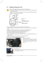
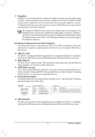
1-8 Onboard Buttons, Switches and LEDs BIOS Switch and BIOS LED Indicators The BIOS switch (SW4) allows users to easily select a different BIOS for boot up or overclocking, helping to reduce BIOS failure during overclocking. The LED indicator (MBIOS_LED/BBIOS_LED) shows which BIOS is active. BIOS Switch: SW4 1: Main BIOS (Boot from the main BIOS) 3: Backup BIOS (Boot from the backup BIOS) BIOS LED Indicators: BBIOS_LED (The backup BIOS is active) MBIOS_LED (The main BIOS is active) VVoollttaaggee mmeeaassuurreemmeenntt ppooiinnttss((GG11..SSnniippeerr 33)) BBIIOOSS SSwwiittcchheerr ((SSWW44)) DDIIPP 11 22 33 PPCCIIee ppoowweerr ccoonnnneeccttoorr ((SSAATTAA))((XX5588AA--OOCC)) DIDPIP 1 12 23 3 11 Quick Buttons This motherboDDaIIPPrd has 3 quick buttons: power button, reset button and clearing CMOS bu1 tton. The power button and reset bu1t1t22o33n allow users to quickly turn on/off or reset the computer in an open-case environment when they want to change hardware components or conduct hardware testing. Use this button to clear the CMOS values (e.g. date information and BIOS configuration) and reset the CMOS values to factory defaults when needed. PPWWMM SSwwiittcchh ((XX5588AA--OOCC)) VVoollttaaggee mmeeaassuurreemmeenntt mmoodduullee((XX5588AA--OOCC)) PW_SW: Power button 1 1 RST_SW: Reset button CMOS_SW: Clear CMOS Button FF__UUSSBB3300 TTPPMM ww//hhoouussiinngg DIDPIP 1 12 23 3 11 BBIIOOSS SSwwiittcchheerr ((XX5588AA--OOCC)) 1 1 MM__SSAATTAA DDBB__PPOORRTT FF__PPAANNEELL((NNHH)) FF__AAUUDDIIOO((HH)) •• Always turn off your computer and unplug the power cord from the power outlet before clearing the CMOS values. •• After system restart, go to BIOS Setup to load factory defaults (select Load Optimized Defaults) or manually configure the BIOS settings (refer to Chapter 2, "BIOS Setup," for BIOS configurations). - 23 - Hardware Installation
-
 1
1 -
2
-
3
-
4
-
5
-
6
-
7
-
8
-
9
-
10
-
11
-
12
-
13
-
14
-
15
-
16
-
17
-
 18
18 -
 19
19 -
 20
20 -
 21
21 -
 22
22 -
 23
23 -
 24
24 -
 25
25 -
 26
26 -
 27
27 -
 28
28 -
29
-
30
-
31
-
32
-
33
-
34
-
35
-
36
-
37
-
38
-
39
-
40
-
41
-
42
-
43
-
44
-
45
-
46
-
47
-
48
-
49
-
50
-
51
-
52
-
53
-
54
-
55
-
56
-
57
-
58
-
59
-
60
-
61
-
62
-
63
-
64
-
65
-
66
-
67
-
68
-
69
-
70
-
71
-
72
-
73
-
74
-
75
-
76
-
77
-
78
-
79
-
80
-
81
-
82
-
83
-
84
-
85
-
86
-
87
-
88
-
89
-
90
-
91
-
92
-
93
-
94
-
95
-
96
-
97
-
98
-
99
-
100
-
101
-
102
-
103
-
104
-
105
-
106
-
107
-
108
-
109
-
110
-
111
-
112
-
113
-
114
-
115
-
116
-
117
-
118
-
119
-
120
-
121
-
122
-
123
-
124
-
125
-
126
-
127
-
128
 |
 |
