Gigabyte GA-Z97N-Gaming 5 User Manual - Page 25
SATA3 0/1/2/3/4 SATA 6Gb/s Connectors, F_AUDIO Front Panel Audio Header, Chipset supports RAID 0
 |
View all Gigabyte GA-Z97N-Gaming 5 manuals
Add to My Manuals
Save this manual to your list of manuals |
Page 25 highlights
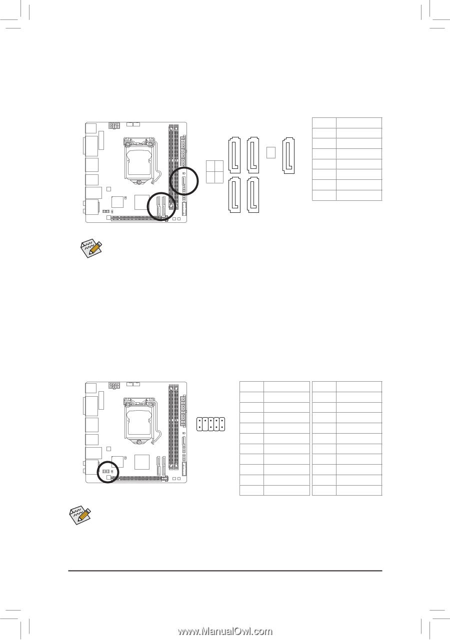
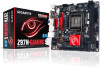
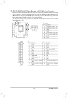
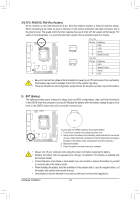
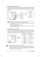
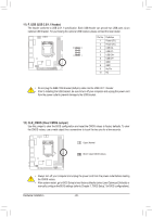
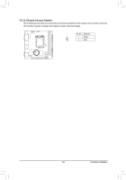
DEBUG PORT DEBUG PORT DEBUG PORT DEBUG PORT DEBUG PORT 6) SATA3 0/1/2/3/4 (SATA 6Gb/s Connectors) The SATA connectors conform to SATA 6Gb/s standard and are compatible with SATA 3Gb/s and SATA 1.5Gb/s standard. Each SATA connector supports a single SATA device. The Intel® Chipset supports RAID 0, RAID 1, RAID 5, and RAID 10. Refer to Chapter 3, "Configuring SATA Hard Drive(s)," for instructions on configuring a RAID array. SATA3 1 1 Pin No. Definition 1 1 GND 2 TXP 4 3 TXN 13 4 GND 02 7 5 RXN 6 RXP 7 GND 7 7 •• A RAID 0 or RAID 1 configuration requires at least two hard drives. If more than two hard drives are to be used, the total number of hard drives must be an even number. •• A RAID 5 configuration requires at least three hard drives. (The total number of hard drives does not have to be an even number.) •• A RAID 10 configuration requires four hard drives. •• To enable hot-plugging for the SATA ports, refer to Chapter 2, "BIOS Setup," "Peripherals\SATA Configuration," for more information. 7) F_AUDIO (Front Panel Audio Header) The front panel audio header supports Intel High Definition audio (HD) and AC'97 audio. You may connect your chassis front panel audio module to this header. Make sure the wire assignments of the module connector match the pin assignments of the motherboard header. Incorrect connection between the module connector and the motherboard header will make the device unable to work or even damage it. For HD Front Panel Audio: For AC'97 Front Panel Audio: Pin No. Definition Pin No. Definition 1 MIC2_L 1 MIC 9 1 2 GND 3 MIC2_R 2 GND 3 MIC Power 10 2 4 -ACZ_DET 5 LINE2_R 4 NC 5 Line Out (R) 6 GND 6 NC 7 FAUDIO_JD 7 NC 8 No Pin 8 No Pin 9 LINE2_L 9 Line Out (L) 10 GND 10 NC •• The front panel audio header supports HD audio by default. •• Audio signals will be present on both of the front and back panel audio connections simultaneously. •• Some chassis provide a front panel audio module that has separated connectors on each wire instead of a single plug. For information about connecting the front panel audio module that has different wire assignments, please contact the chassis manufacturer. - 25 - Hardware Installation
-
 1
1 -
2
-
3
-
4
-
5
-
6
-
7
-
8
-
9
-
10
-
11
-
12
-
13
-
14
-
15
-
16
-
17
-
18
-
19
-
 20
20 -
 21
21 -
 22
22 -
 23
23 -
 24
24 -
 25
25 -
 26
26 -
 27
27 -
 28
28 -
 29
29 -
 30
30 -
31
-
32
-
33
-
34
-
35
-
36
-
37
-
38
-
39
-
40
-
41
-
42
-
43
-
44
-
45
-
46
-
47
-
48
-
49
-
50
-
51
-
52
-
53
-
54
-
55
-
56
-
57
-
58
-
59
-
60
-
61
-
62
-
63
-
64
-
65
-
66
-
67
-
68
-
69
-
70
-
71
-
72
-
73
-
74
-
75
-
76
-
77
-
78
-
79
-
80
 |
 |