Gigabyte GS-R1233-RH Manual
Gigabyte GS-R1233-RH Manual
 |
View all Gigabyte GS-R1233-RH manuals
Add to My Manuals
Save this manual to your list of manuals |
Gigabyte GS-R1233-RH manual content summary:
- Gigabyte GS-R1233-RH | Manual - Page 1
GS-R1233-RH 1U Rack Mount Server System Installation Guide AMD Opteron™ Socket F Dual Processor Motherboard Rev. 1.0 - Gigabyte GS-R1233-RH | Manual - Page 2
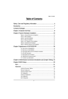
2-6: Hard Disk Drive Installation 16 Step 2-7: FAN Duct Removal and Installation 17 Chapter 3 Appearance of GS-R1233-RH 18 3-1: Front View of GS-R1233-RH 18 3-2: Rear View of GS-R1233-RH 18 3-3: Front Bazel Switch and LED Indicators Introduction 19 3-4: LAN LED Description 20 3-5: Back plane - Gigabyte GS-R1233-RH | Manual - Page 3
GS-R1233-RH Rack Mount Server DMI Event Logging ...48 Hardware Monitor ...50 Security ...53 Server ...55 System Management ...56 Console Redirection ...57 Boot ...59 Exit ...60 3 - Gigabyte GS-R1233-RH | Manual - Page 4
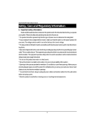
GS-R1233-RH Rack Mount Server Safety, Care and Regulatory Information / Important safety information Read and follow all instructions marked on the product and in the documentation before you operate your system. Retain all safety and operating instructions for future use. * The product should be - Gigabyte GS-R1233-RH | Manual - Page 5
. This equipment generates, uses, and can radiate radio frequency energy and, if not installed and used in accordance with the instruction manual, may cause harmful interference to radio communications. Operation of this equipment in a residential area is likely to cause harmful interference - Gigabyte GS-R1233-RH | Manual - Page 6
GS-R1233-RH Rack Mount Server NOTICE: The Load Number (LN) assigned to each terminal device denotes the percentage of the total load to be . ™ Replace only with the same or equivalent type recommended by the manufacturer. ™ Dispose of used batteries according to the manufacturer's instructions. 6 - Gigabyte GS-R1233-RH | Manual - Page 7
GS-R1233-RH Rack Mount Server Introduction Welcome to Gigabyte GS-R1233-RH Rack mount Server System Installation Guide. The guide provides instructions for configuration hardware for the GS-R1233-RH your system. This installation guide will assist you in installing all the essential components for - Gigabyte GS-R1233-RH | Manual - Page 8
GS-R1233-RH Rack Mount Server Chapter 1 Features Summary Motherboard Processor Supported Chipset System Memory: Memory Capacity Memory Type DIMM Size Error Correction: Expansion Slot SATA RAID controller Cooling Fans: Integrated LANs: Controller Integrated Graphics: Controller Graphics - Gigabyte GS-R1233-RH | Manual - Page 9
Introduction BIOS Type y Phoenix BIOS on 8Mb flash ROM Server Management Functions: (Optional device) BMC Chip y H8S IPMI 2.0 controller Failure Detection y IPMI 2.0 specification of Server management Event Logging y 9.216KB Nonvolatile Memory to Log System Failure Events Remote Management - Gigabyte GS-R1233-RH | Manual - Page 10
GS-R1233-RH Rack Mount Server Chapter 2 System Hardware Installation Please observe the safety information in chapter "Important Safety Information" Do not expose the server to extreme environmental - Gigabyte GS-R1233-RH | Manual - Page 11
Step 2-2: CPU Installation Hardware Installation Process Please make sure the CPU type and speed that are supported by the motherboard. Step 1 Raise the metal locking lever on the socket. Insert the CPU with the correct orientation. Step 2 The CPU only fits in - Gigabyte GS-R1233-RH | Manual - Page 12
GS-R1233-RH Rack Mount Server Step 2-3: Heat Sink Installation Step 1 Place the Heat Sink on the CPU. Before putting the heat sink on the CPU, please well - Gigabyte GS-R1233-RH | Manual - Page 13
Step 2-4: Memory Installation Hardware Installation Process Step 1. Insert the DIMM memory module vertically into the DIMM slot, and push it down. Step 2. Close the plastic clip at both edges of the DIMM slots to lock the DIMM module. NOTE! DIMM must be populated in order starting from DIMM_A1 or - Gigabyte GS-R1233-RH | Manual - Page 14
GS-R1233-RH Rack Mount Server DIMM Population Table DIMM: Single or dual Rank Max. capacity 4GB. CPU1 Single Channel (One DIMM) Dual Channel (2 DIMMs) Dual Channel (4 DIMMs) - Gigabyte GS-R1233-RH | Manual - Page 15
GS-R1233-RH Rack Mount Server Step 2-5: PCI Expansion Card Installation GS-R1231-RH provides expansion riser slots , then pull it out from the server chassis. Step 3 Align the expansion card with the guiding groove. Slide the expansion card into the slot until the card firmly seats. Step 4 Align - Gigabyte GS-R1233-RH | Manual - Page 16
Hardware Installation Process Step 2-6: Hard Disk Drive Installation Step 1 Press the release button. Step 2 Pull the blank out of the drive bay. Step 3 Slide hard disk into blank. Step 4 Secure it with screws. Step 5 Slide the blank into the bay until it locks into place. Connect cable and power. 1 - Gigabyte GS-R1233-RH | Manual - Page 17
GS-R1233-RH Rack Mount Server Step 2-7: FAN Duct Removal and Installation Step 1 Align the fan duct with the guiding groove. Push down the fan duct into system ntil the its firmly seats. Guiding groove 17 - Gigabyte GS-R1233-RH | Manual - Page 18
System Appearance Chapter 3 Appearance of GS-R1233-RH 3-1: Front View of GS-R1233-RH YZ X X Hot-Swap SATA HDDs Y USB connectors Z Front panel switch and LEDs 3-2: Rear View of GS-R1233-RH Y _ X Z\ [ ] ^ X Power cord Y Mouse connector Z Keyboard connector [ COM port \ VGA port ] USB - Gigabyte GS-R1233-RH | Manual - Page 19
GS-R1233-RH Rack Mount Server 3-3: Front Bazel Switch and LED Indicators Introduction LAN1/2 Activities NMI switch System LED ID BTN&LED Reset switch HDD Power Name Power - Gigabyte GS-R1233-RH | Manual - Page 20
3-4: LAN LED Description LED Description Name Color LAN Green Link/Activity Green - 10 LAN - Speed 100 LAN Green Speed Green GbE LAN Yellow Speed Yellow Condition ON BLINK OFF OFF ON BLINK ON BLINK Description LAN Link / no Access LAN Access Idle 10Mbps connection 100Mbps connection - Gigabyte GS-R1233-RH | Manual - Page 21
GS-R1233-RH Rack Mount Server 3-5: Back plane board Information Hard Disk Drive 4 Hard Disk Drive 3 Hard Disk Drive 2 Hard Disk Drive 1 3-6: Hard Disk Drive LED Description Color Green -- Hard Disk LED Condition Blink Off Description Hard Disk Drive Access No Access and No HDD Fault 21 - Gigabyte GS-R1233-RH | Manual - Page 22
3-7: Connector Icon Description Connector Icon Description Suggest Icon Description Keyboard Mouse VGA COM LAN USB 22 - Gigabyte GS-R1233-RH | Manual - Page 23
GS-R1233-RH Rack Mount Server Chapter 4 Motherboard Connectors Introduction and Jumper Setting 9 2 8 10 1 3 11 45 6 7 1. ATX_L1 2. ATX_12V1 3. F_USB1 (Front USB cable connector) 4. SATA0 (SATA data cable connector) 5. - Gigabyte GS-R1233-RH | Manual - Page 24
to the CPU. If the ATX_12V power connector is not connected, the system will not start. Caution! Please use a power supply that is able to support the system voltage requirements. It is recommended that a power supply that can withstand high power consumption be used (300W or greater). If a power - Gigabyte GS-R1233-RH | Manual - Page 25
GS-R1233-RH Rack Mount Server 3 ) F_USB1 (Front USB Connectors) Be careful with the polarity of the front USB connector. Check the pin assignment carefully while you connect - Gigabyte GS-R1233-RH | Manual - Page 26
8 )BP2 (SMBus connector for backplane board) Jumper Setting 6 Pin No. Definition 1 BP_SMBCLK 2 BP_SMBDAT 3 BPFAN_PWM 4 BP_HDLED 5 -EXT_SMI 1 6 GND 26 - Gigabyte GS-R1233-RH | Manual - Page 27
GS-R1233-RH Rack Mount Server 9 ) F_Panel (2X12 Pins Front Panel connector) Please connect the power LED, PC speaker, reset switch and power switch of your chassis front - Gigabyte GS-R1233-RH | Manual - Page 28
10 )JP1 (BIOS Recovery Jumper) Jumper Setting 1 1-2 Close: Enable BIOS recovery function 1 2-3 Close: Disabe this function (Default setting) 11 )CLR_CMOS1 (Clear CMOS Jumper) You may clear the CMOS data to restore its default values by this jumper. Default value doesn't include the "Shunter" - Gigabyte GS-R1233-RH | Manual - Page 29
Chapter 5 BIOS Setup BIOS Setup BIOS Setup is an overview of the BIOS Setup Program. The program that allows users to modify the basic system configuration. This type of information is stored in battery-backed CMOS RAM so that it retains the Setup information when the power is turned off. - Gigabyte GS-R1233-RH | Manual - Page 30
GS-R1233-RH Rack Mount Server GETTINGHELP Main Menu The on-line description of the highlighted setup function is displayed at the bottom of the screen. Status Page - Gigabyte GS-R1233-RH | Manual - Page 31
BIOS Setup Main Once you enter Phoenix BIOS Setup Utility, the Main Menu (Figure 1) will appear on the screen. Use arrow keys to select among the items and press to accept or enter the sub-menu. Figure 1: Main System Time The time is calculated based on the 24-hour military time clock. Set - Gigabyte GS-R1233-RH | Manual - Page 32
GS-R1233-RH Rack Mount Server Processor Information These following items display all information of current CPU Type, CPU Speed, and CPU Count. These items are display-only which is determined by POST (Power On Self Test) of the BIOS. Total Memory Size This item identifies the total memory size. 32 - Gigabyte GS-R1233-RH | Manual - Page 33
Advanced BIOS Setup About This Section: Advanced With this section, allowing user to configure your system for basic operation. User can change the processor options, chipset configuration, PCI configuration and chipset control. Figure 2: Advanced 33 - Gigabyte GS-R1233-RH | Manual - Page 34
GS-R1233-RH Rack Mount Server Advanced Processor Options Figure 2-1: Advanced Processor Option 34 - Gigabyte GS-R1233-RH | Manual - Page 35
GS-R1233-RH Rack Mount Server Advanced Processor Option This category includes the information of CPU Type, CPU Speed, CPU1/CPU2 ID, CPU1/CPU2 L2 Cache, CPU Type, - Gigabyte GS-R1233-RH | Manual - Page 36
BIOS Setup ACPI SRAT Table Enabled Enable ACPI 2.0 static resources affinity table for ccNUMA systems. (Default setting) Disabled Disable this function. Optimize Performance Unganged Select Unganged mode as optimize performance. (Default setting) Ganged Select Ganged mode as optimize - Gigabyte GS-R1233-RH | Manual - Page 37
GS-R1233-RH Rack Mount Server Memory Configuration Figure 2-2: Memory Configuration Syetem Memory/Extended Memory These category is display-only which is determined by POST (Power On Self - Gigabyte GS-R1233-RH | Manual - Page 38
Advanced Chipset Control BIOS Setup Figure 2-3: Advanced Chipset Control Wake on Keyboard/Mouse This item allows you to set the enable/disable for powering-on the system by keyboard and mouse. Enabled Wake on Keyboard/Mouse. (Default setting) Disabled Disable this function. Note: This item - Gigabyte GS-R1233-RH | Manual - Page 39
GS-R1233-RH Rack Mount Server Wake On RTC Alarm You can set "RTC" items to enabled and key in Data/time to power on system. Enabled Enable alarm function to POWER ON system. Disabled Disable this function. (Default setting) 39 - Gigabyte GS-R1233-RH | Manual - Page 40
PCI Configuration BIOS Setup Figure 2-4: PCI Configuration PCI Slot 1Option ROM Enabled Enable this item to initialize device expansion ROM. (Defualt setting) Disabled Disable this function. Onboard LAN1 Control Enabled Enable onboard LAN1 device. (Defualt setting) Disabled Disable this - Gigabyte GS-R1233-RH | Manual - Page 41
GS-R1233-RH Rack Mount Server Onboard LAN2 Control Enabled Enable onboard LAN1 device. (Defualt setting) Disabled Disable this function. LAN2 Optiona ROM Scan Enabled Enableing this item - Gigabyte GS-R1233-RH | Manual - Page 42
I/O Device Configuration BIOS Setup Figure 2-5: I/O Device Configuration Serial Port A This allows users to configure serial prot A address by using this option. Enabled Set serial port A address to 3F8/IRQ4. Disabled No configuration. Auto Auto-detection. (Default setting) Serial Port B This - Gigabyte GS-R1233-RH | Manual - Page 43
GS-R1233-RH Rack Mount Server PS/2 Mouse Set this option 'Enabled' to allow BIOS support for a PS/2 - type mouse. Enabled 'Enabled' forces the PS/2 mouse port to be enabled regardless if a mouse is present. (Default setting) Disabled 'Disabled' prevents any - Gigabyte GS-R1233-RH | Manual - Page 44
IDE Configuration BIOS Setup Figure 2-6: IDE Configuration Primary Master, Slave/SATA0~5 The category identifies the types of hard disk from drive C to F and SATA 0~SATA 5 are installed in the computer. System will automatically detect HDD type. Note that the specifications of your drive must - Gigabyte GS-R1233-RH | Manual - Page 45
and to the device occurs multiple sectors at a time if the device supports it. LBA/Large Mode 32-Bit I/O Transfer Mode Ultra DMA Mode This field shows if the device type in the specific IDE channel support LBA Mode Enable this function to max imize the IDE data transfer rate - Gigabyte GS-R1233-RH | Manual - Page 46
. (Default setting) Multiprocessor Specification This option allows user to configure the multiprocessor(MP) specification revision level. Some operating system will require 1.1 for compatibility reasons. 1.4 Support MPS Version 1.4 . (Default setting) 1.1 Support M PS Version 1.1. 46 - Gigabyte GS-R1233-RH | Manual - Page 47
GS-R1233-RH Rack Mount Server Post Error Pause All Errors Whenever the BIOS detects a non-fatal error the system will be stopped. All, But Keyboard The system - Gigabyte GS-R1233-RH | Manual - Page 48
DMI Event Logging BIOS Setup Figure 2-8: DMI Event Logging Event log vaildity/Event log capacity These two items display the current status of Event log vaildity and Event log capacity. View DMI event log Press [Enter] to view DMI event log. Event Logging Enabled Disabled Select Enabled to - Gigabyte GS-R1233-RH | Manual - Page 49
GS-R1233-RH Rack Mount Server ECC Memory Logging Enabled Select Enabled to allow logging of killed memory. (Default setting) Disabled Disable this function. Mark DMI events as - Gigabyte GS-R1233-RH | Manual - Page 50
Hardware Monitor BIOS Setup Figure 2-9: Hardware Monitor 50 - Gigabyte GS-R1233-RH | Manual - Page 51
GS-R1233-RH Rack Mount Server 51 - Gigabyte GS-R1233-RH | Manual - Page 52
CPU1/CPU 2/ SystemTemperature Display the current CPU1/2 temperature and system temperature. BIOS Setup Voltage Monitor: VCORE1/2, 3.3V, 5V, -12V, +12V, 1.5V, P1 1.8V, P2 1.8V, P1 0.9V, P2 0.9V Detect system's voltage status automatically. FAN Monitor: SYS FAN1A/1B,SYS FAN2A/2B,SYS FAN3A/3B, SYS - Gigabyte GS-R1233-RH | Manual - Page 53
GS-R1233-RH Rack Mount Server Security * About This Section: Security In this section, user can set either supervisor or user passwords, or both for different level of - Gigabyte GS-R1233-RH | Manual - Page 54
BIOS Setup Set User Password You can only enter but do not have the right to change the options of the setup menus. When you select this function, the following message will appear at the center of the screen to assist you in creating a password. Type the password up to 6 characters in lengh and - Gigabyte GS-R1233-RH | Manual - Page 55
GS-R1233-RH Rack Mount Server Server Figure 4: Server 55 - Gigabyte GS-R1233-RH | Manual - Page 56
System Management BIOS Setup Figure 4-1: System Management Server Management This category allows user to view the server management features. Including information of BIOS Version, System Product Name, System Serial Number, BaseBoard ID, Main Board Serial Number, and, System ID. All items in this - Gigabyte GS-R1233-RH | Manual - Page 57
GS-R1233-RH Rack Mount Server Console Redirection Figure 4-2: Remote Access Configuration COM Port Adress If this option is set to enabled, it will use a port on the - Gigabyte GS-R1233-RH | Manual - Page 58
Flow Control This option provide user to enable the flow control function. None Not supported. XON/OFF Software control. CTS/RTS Hardware control. (Default setting) BIOS Setup Continue C.R. after POST This option allows user to enable console redirection after O.S has - Gigabyte GS-R1233-RH | Manual - Page 59
GS-R1233-RH Rack Mount Server Boot Figure 5: Boot Boot Device Priority This field determines which type of device the system attempt to boot from after BIOS POST - Gigabyte GS-R1233-RH | Manual - Page 60
Exit BIOS Setup Figure 6: Exit * About This Section: Exit Once you have made the changes in the BIOS setup items, you have to save your changes and exit BIOS setup program. Select "Exit" from the menu bar, to display the following sub-menu. Save Changes and Exit Discard Changes and Exit Discard - Gigabyte GS-R1233-RH | Manual - Page 61
GS-R1233-RH Rack Mount Server Exit Saving Changes This option allows user to exit system setup with saving the changes. Press on this item to ask - Gigabyte GS-R1233-RH | Manual - Page 62
BIOS Setup Exit Discarding Changes This option allows user to exit system setup without changing any previous settings values in CMOS. The previous selection remain in effect. This will exit the Setup Utility and restart your compuetr when selecting this option. Load Setup Default This option allows - Gigabyte GS-R1233-RH | Manual - Page 63
GS-R1233-RH Rack Mount Server Discard Changes This option allows user to exit system setup without changing any previous settings values in CMOS. The previous selection remain in effect. This will exit the Setup Utility and restart your compuetr when selecting this option. 63 - Gigabyte GS-R1233-RH | Manual - Page 64
BIOS Setup Save Changes This option allows user to save setup dat ato CMOS. When you press on this item, you will get a confirmation dialog box with a message as below: Press [Yes] to save setup daya to CMOS. 64
-
 1
1 -
 2
2 -
 3
3 -
 4
4 -
 5
5 -
 6
6 -
 7
7 -
8
-
9
-
10
-
11
-
12
-
13
-
14
-
15
-
16
-
17
-
18
-
19
-
20
-
21
-
22
-
23
-
24
-
25
-
26
-
27
-
28
-
29
-
30
-
31
-
32
-
33
-
34
-
35
-
36
-
37
-
38
-
39
-
40
-
41
-
42
-
43
-
44
-
45
-
46
-
47
-
48
-
49
-
50
-
51
-
52
-
53
-
54
-
55
-
56
-
57
-
58
-
59
-
60
-
61
-
62
-
63
-
64
 |
 |

System Installation Guide
GS-R1233-RH
1U Rack Mount Server
AMD Opteron
™
Socket F Dual Processor Motherboard
Rev. 1.0