Gigabyte H510M H User Manual - Page 17
F_U32 USB 3.2 Gen 1 Header, F_USB1 USB 2.0/1.1 Header, SPI_TPM Trusted Platform Module Header
 |
View all Gigabyte H510M H manuals
Add to My Manuals
Save this manual to your list of manuals |
Page 17 highlights
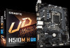
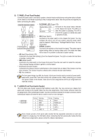
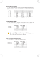
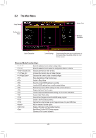
SS U F_ 1 23 1 12345 F_USB30 F_ U F_ 10) F_U32 (USB 3.2 Gen 1 Header) The header conforms to USB 3.2 Gen 1 and USB 2.0 specification and can provide two USB ports. For purchasing the optional 3.5" front panel that provides two USB 3.2 Gen 1 ports, please contact the local dealer. 20 _ B 11 1 Pin No. Definition Pin No. Definition Pin No. Definition 1 VBUS 8 D1- 15 SSTX2- 2 SSRX1- 9 D1+ 16 GND 3 SSRX1+ B_ 4 GND 5 SBSTSX_ 1- B 10 6 SSTX1+ 7 GND 10 NC B SS 11 D2+ 12 D21 13 GND 14 SSTX2+ 17 SSRX2+ 18 SSRX219 VBUS 20_S No Pin 1 23 1 1 23 1 S B_ S B 11) F_USB1 (USB 2.0/1.1 Header) S The header conforms to USB 2.0/1.1 specification. Each USB header can provide two USSB ports via an optional USB bracket. For purchasing the optional USB bracket, please contact the local dealer. 1 23 _S S_ _ 9 B 10 _U _ B S Pin No. Definition Pin No. Definition 1 1 Power (5V) 6 USB DY+ 2 2 Power (5V) 7 GND 3 USB DX- 8 GND 4 USB DY- 9 No Pin 5 USB DX+ 10 NC F F_USB3 F •• Do not plug the IEEE 1394 bracket (2x5-pin) cable into the USB 2.0/1.1 header. S •3• Prior to installing the UBSSBSbrackSet, be sure to turn off your cUomputer and unplug _the_ pow3er cord from the power outlet to prevent damage to the USB bracket. _0 S _ _ 12) SYoPuIS_m_TaPyMco(nTnreucst taendSPPlIaTtPfoMrm(TrMusoteddSuPleFlatHfoermadMeor)dule) to this h_eader. _F Pin No. Definition Pin No. Definition 11 1 1 Data Output 7 Chip Select 12 2 2 Power (3.3V) 8 GND 3 B_ No Pin 4 NC S 5 Data Input 9 _S 10 _ 101 IRQ_ NC F NC 6 CLK 12 RST _ _B S F_ S_ - 17 - B_ _ S F_ F_ S F_USB _
-
 1
1 -
2
-
3
-
4
-
5
-
6
-
7
-
8
-
9
-
10
-
11
-
 12
12 -
 13
13 -
 14
14 -
 15
15 -
 16
16 -
 17
17 -
 18
18 -
 19
19 -
 20
20 -
 21
21 -
 22
22 -
23
-
24
-
25
-
26
-
27
-
28
-
29
-
30
-
31
-
32
-
33
-
34
-
35
-
36
-
37
-
38
-
39
-
40
-
41
 |
 |
