Gigabyte Z390 AORUS MASTER G2 Edition User Manual - Page 21
Back Panel Connectors, Power Button, Clear CMOS Button, SMA Antenna Connectors 2T2R - test
 |
View all Gigabyte Z390 AORUS MASTER G2 Edition manuals
Add to My Manuals
Save this manual to your list of manuals |
Page 21 highlights
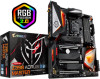
1-7 Back Panel Connectors Power Button The power button allows users to quickly turn on/off the computer in an open-case environment when they want to change hardware components or conduct hardware testing. This button is a power button by default, refer to Chapter 2, "BIOS Setup," "Power," for more information. Clear CMOS Button Use this button to clear the CMOS values (e.g. BIOS configuration) and reset the CMOS values to factory defaults when needed. •• Always turn off your computer and unplug the power cord from the power outlet before using the clear CMOS button. •• Do not use the clear CMOS button when the system is on, or the system may shutdown and data loss or damage may occur. •• After system restart, go to BIOS Setup to load factory defaults (select Load Optimized Defaults) or manually configure the BIOS settings (refer to Chapter 2, "BIOS Setup," for BIOS configurations). SMA Antenna Connectors (2T2R) Use this connector to connect an antenna. Tighten the antenna cables to the antenna connectors and then move the antenna to a place where the signal is good. USB 2.0/1.1 Port The USB port supports the USB 2.0/1.1 specification. Use this port for USB devices. USB 3.1 Gen 1 Port The USB 3.1 Gen 1 port supports the USB 3.1 Gen 1 specification and is compatible to the USB 2.0 specification. You can connect a USB DAC to this port or use this port for USB devices. HDMI Port The HDMI port supports HDCP 2.2 and Dolby TrueHD and DTS HD Master Audio formats. It also supports up to 192KHz/16bit 8-channel LPCM audio output. You can use this port to connect your HDMI-supported monitor. The maximum supported resolution is 4096x2160@30 Hz, but the actual resolutions supported are dependent on the monitor being used. After installing the HDMI device, make sure to set the default sound playback device to HDMI. (The item name may differ depending on your operating system.) •• When removing the cable connected to a back panel connector, first remove the cable from your device and then remove it from the motherboard. •• When removing the cable, pull it straight out from the connector. Do not rock it side to side to prevent an electrical short inside the cable connector. - 21 - Hardware Installation
-
 1
1 -
2
-
3
-
4
-
5
-
6
-
7
-
8
-
9
-
10
-
11
-
12
-
13
-
14
-
15
-
 16
16 -
 17
17 -
 18
18 -
 19
19 -
 20
20 -
 21
21 -
 22
22 -
 23
23 -
 24
24 -
 25
25 -
 26
26 -
27
-
28
-
29
-
30
-
31
-
32
-
33
-
34
-
35
-
36
-
37
-
38
-
39
-
40
-
41
-
42
-
43
-
44
-
45
-
46
-
47
-
48
-
49
-
50
-
51
-
52
-
53
-
54
-
55
-
56
-
57
-
58
-
59
-
60
-
61
-
62
-
63
-
64
-
65
-
66
-
67
-
68
-
69
-
70
-
71
-
72
-
73
-
74
-
75
-
76
-
77
-
78
-
79
-
80
-
81
-
82
-
83
-
84
-
85
-
86
-
87
-
88
-
89
-
90
-
91
-
92
-
93
-
94
-
95
-
96
-
97
-
98
-
99
-
100
-
101
-
102
-
103
-
104
-
105
-
106
-
107
-
108
-
109
-
110
-
111
-
112
-
113
-
114
-
115
-
116
-
117
-
118
-
119
-
120
-
121
-
122
-
123
-
124
-
125
-
126
-
127
-
128
-
129
-
130
-
131
-
132
-
133
-
134
-
135
-
136
-
137
-
138
-
139
-
140
 |
 |
