Gigabyte Z590 VISION D User Manual - Page 26
CPU_FAN/SYS_FAN1/2/3/4 Fan Headers, SYS_FAN5/6_PUMP System Fan/Water Cooling Pump Headers
 |
View all Gigabyte Z590 VISION D manuals
Add to My Manuals
Save this manual to your list of manuals |
Page 26 highlights
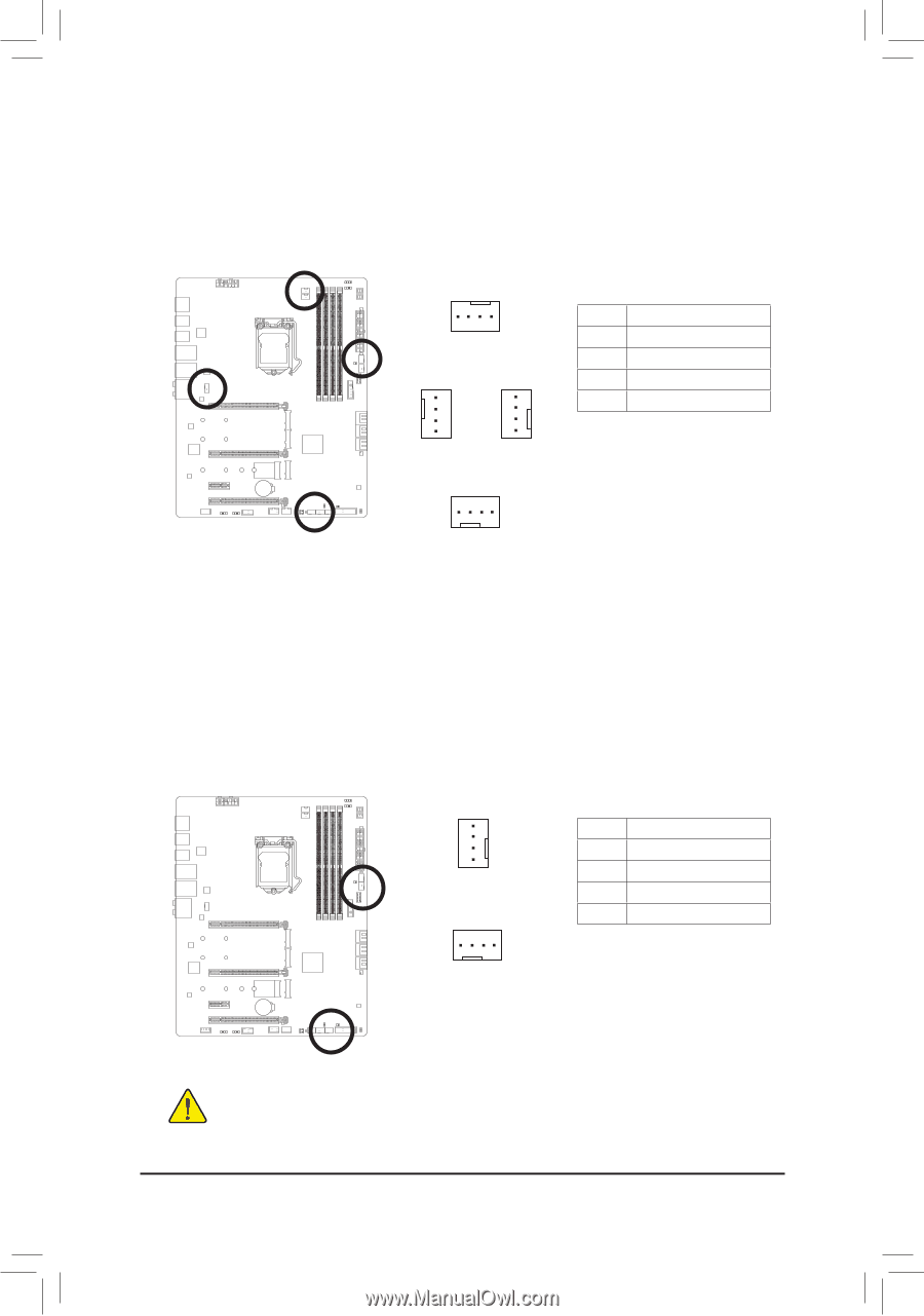
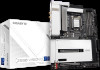
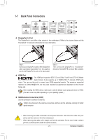
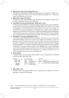
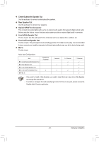
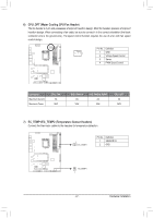
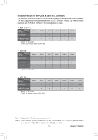
3/4) CPU_FAN/SYS_FAN1/2/3/4 (Fan Headers) All fan headers on this motherboard are 4-pin. Most fan headers possess a foolproof insertion design. When connecting a fan cable, be sure to connect it in the correct orientation (the black connector wire is the ground wire). The speed control function requires the use of a fan with fan speed control design. For optimum heat dissipation, it is recommended that a system fan be installed inside the chassis. 1 CPU_FAN 1 SYS_FAN1 1 SYS_FAN2 Pin No. 1 2 3 4 Definition GND Voltage Speed Control Sense PWM Speed Control 1 SYS_FAN3/SYS_FAN4 5) SYS_FAN5/6_PUMP (System Fan/Water Cooling Pump Headers) The fan/pump headers are 4-pin. Most fan headers possess a foolproof insertion design. When connecting a fan cable, be sure to connect it in the correct orientation (the black connector wire is the ground wire). The speed control function requires the use of a fan with fan speed control design. For optimum heat dissipation, it is recommended that a system fan be installed inside the chassis. The header also provides speed control for a water cooling pump, refer to Chapter 2, "BIOS Setup," "Smart Fan 6," for more information. 1 SYS_FAN5_PUMP 1 SYS_FAN6_PUMP Pin No. 1 2 3 4 Definition GND Voltage Speed Control Sense PWM Speed Control •• Be sure to connect fan cables to the fan headers to prevent your CPU and system from overheating. Overheating may result in damage to the CPU or the system may hang. •• These fan headers are not configuration jumper blocks. Do not place a jumper cap on the headers. Hardware Installation - 26 -
-
 1
1 -
2
-
3
-
4
-
5
-
6
-
7
-
8
-
9
-
10
-
11
-
12
-
13
-
14
-
15
-
16
-
17
-
18
-
19
-
20
-
 21
21 -
 22
22 -
 23
23 -
 24
24 -
 25
25 -
 26
26 -
 27
27 -
 28
28 -
 29
29 -
 30
30 -
 31
31 -
32
-
33
-
34
-
35
-
36
-
37
-
38
-
39
-
40
-
41
-
42
-
43
-
44
-
45
-
46
-
47
-
48
-
49
-
50
-
51
-
52
-
53
-
54
-
55
-
56
-
57
-
58
-
59
-
60
-
61
-
62
-
63
-
64
-
65
-
66
-
67
-
68
-
69
-
70
-
71
-
72
-
73
-
74
-
75
-
76
-
77
-
78
-
79
-
80
-
81
-
82
-
83
-
84
-
85
-
86
-
87
-
88
-
89
-
90
-
91
-
92
-
93
-
94
-
95
-
96
-
97
-
98
-
99
-
100
-
101
-
102
-
103
-
104
-
105
-
106
-
107
-
108
-
109
-
110
-
111
-
112
 |
 |