Gigabyte Z690 UD AX DDR4 User Manual - Page 26
F_AUDIO Front Panel Audio Header, SPDIF_O S/PDIF Out Header, Pin No., 5VDUAL, No Pin, SPDIFO, MIC L
 |
View all Gigabyte Z690 UD AX DDR4 manuals
Add to My Manuals
Save this manual to your list of manuals |
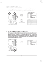
Page 26 highlights
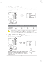
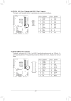
_ B S_ B B 1 23 1 23 1 1 23 1 23 3 U _ _ S B_ 12) F_AUDIO (Front Panel Audio HBeader) The front panel audio header supports High Definition audio (HD). You may connect your chassis front panel audio module to this header. Make sure the wire assignments of the module connector match the pin assignments of the motherboard header. Incorrect connection between the module connector and the motherboard header will make the device unable to work or even damage it. _S F_ U __ 3 S_ _ Pin No. Definition B 1 MIC L 9 1 _U _ B 10 2 2 GND F_3 MIC R 4 NC 5 Head Phone R 6 MIC Detection F_ F F_USB3 F 7 SENSE_SEND 8 No Pin 9 Head Phone L 10 Head Phone Detection _0 1 23 1 Some chassis provide a front panelBaSudSio module that has separated connectors on each wire instead oBf_a_ sin_gBle plug. For inform_ ation about conSn_ecting the front panel audio module that has different wire assignments, please contact the chassi1s manufacturer. _S _F 1 23 1 _ 13) SPDIF_O (S/PDIF Out Header) B This header supports S/PDIF digital outpuSt, which allows you to connect a S/PDIF digital audio cable to output digital audio from your motherboard to the supported audio devices. For information about connecting the digital audio cable, carefully read the manual for your audio devices. _0 F S S F_ B S S_F B_ 1 23 Pin No. Definition 1 5VDUAL 2 No Pin 3 SPDIFO 1 4 GND S B_ B _S S_ _ B S3 _ B SS S SF U _ __ 3 _U _ B _3 U F_USB3 F F_USB3 F_USB30 3 - 26 - B_ _ _B _ S_ B_ S _S _
-
 1
1 -
2
-
3
-
4
-
5
-
6
-
7
-
8
-
9
-
10
-
11
-
12
-
13
-
14
-
15
-
16
-
17
-
18
-
19
-
20
-
 21
21 -
 22
22 -
 23
23 -
 24
24 -
 25
25 -
 26
26 -
 27
27 -
 28
28 -
 29
29 -
 30
30 -
 31
31 -
32
-
33
-
34
-
35
-
36
-
37
-
38
-
39
-
40
-
41
-
42
-
43
-
44
 |
 |
