Haier AB122FDAHA User Manual - Page 7
Troubleshooting, Indoor unit installation
 |
View all Haier AB122FDAHA manuals
Add to My Manuals
Save this manual to your list of manuals |
Page 7 highlights
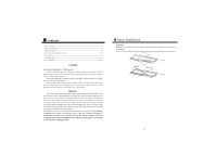
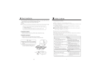
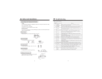
Troubleshooting Confirm and verify When failure occurs, use the remote controller to display the corresponding error code. Checking 1.Press the ì Checkî switch on the remote controller for 1-2 seconds, ì Checkî will appear, and the unit number and the error code will be displayed on the remote controller. 2.The displayed number is the error unit number. 3.Example is listed as follows: Normal: One error: Two errors: The signs will be displayed for a very short time. If not seen clearly, press the ì Checkî switch again. Fault codes and error place Fault code 16 Indoor unit installation Put the nut on the screw bolt and suspend it on the T slot of the suspension part of the unit. Keep level of the body (within 5mm) with a gradoenter. Make sure and adjust the positions of the unit and the ceiling opening as well as the height of the unit with the installation template. 1. The bottom of the unit is 58mm from the lower ceiling surface. (four corners) 2. Make sure that the front side of the indoor unit (tube side) is 95mm from the ceiling and the back side of the unit (opposite side) is 35mm from the ceiling with the template. gradienter tighten up with a nut suspension screw (M10) nut (M10) parts other than M10 flat gasket are provided during installation M10 flat gasket M10 flat gasket for safety, please mount according to this diagram nut (M10) indoor unit ceiling 15 58 installation template front side (tube side) lower 95 ceiling surface indoor unit installation template installation template back side (opposite side) 35 Installation of the panel Tighten the upper nut to fix the indoor unit. Mount the panel after tubing and wiring installation. Please refer to P18-21 of this manual for the panel installation. Before installation, make sure that the positions of the indoor unit and the ceiling opening are correct. Requirements: There is no space between the panel and the ceiling and between the panel and the indoor unit, otherwise, dew or water leak may occur. Installation of remote controller Please refer to the installation manual for the installation of the remote controller. 5
-
 1
1 -
 2
2 -
 3
3 -
 4
4 -
 5
5 -
 6
6 -
 7
7 -
 8
8 -
 9
9 -
 10
10 -
 11
11 -
 12
12
 |
 |
