Haier HB6000VD1M22-EP User Manual
Haier HB6000VD1M22-EP Manual
 |
View all Haier HB6000VD1M22-EP manuals
Add to My Manuals
Save this manual to your list of manuals |
Haier HB6000VD1M22-EP manual content summary:
- Haier HB6000VD1M22-EP | User Manual - Page 1
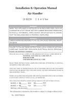
Installation & Operation Manual Air Handler 13 SEER 2 3 4 5 Ton WARNING WHEN THIS APPLIANCE IS INSTALLED IN AN ENCLOSED NFPA 90A & 90B UNIFORM MECHANICAL CODE READ THESE INSTRUCTIONS COMPLETELY BEFORE ATTEMPTING TO INSTALL OR SERVICE THIS APPLIANCE. ONLY FACTORY AUTHORIZED KITS OR ACCESSORIES - Haier HB6000VD1M22-EP | User Manual - Page 2
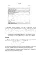
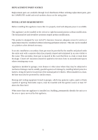
Replacement Parts Source Installation Requirements Air Flow Orientation Horizontal Left-Hand Instructions Refrigerant unit be done so by a certified technician. Should questions arise contact the local EPA office. THIS APPLIANCE IS NOT APPROVED FOR OUTDOOR INSTALLATION THIS APPLIANCE IS NOT TO BE - Haier HB6000VD1M22-EP | User Manual - Page 3
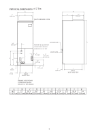
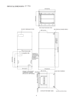
PHYSICAL DIMENSIONS of 2 Ton D 1" C [2.54 cm] PLASTIC BREAKER COVER B E 11" [29 cm] SUCTION LINE A 3.3" [8.3 cm] PRIMARY & SECONDARY CONDENSATE DRAINS- HORIZONTAL 3/4" NPT F K G 2" [5.1 cm] 1.1" [2.9 cm] LIQUID LINE 2" [5.1 cm] TYPICAL 2.4" [ 6 cm] 1.2" [3 cm] H - Haier HB6000VD1M22-EP | User Manual - Page 4
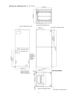
PHYSICAL DIMENSIONS of 3 Ton PLASTIC BREAKER COVER INLET BOTTOM SIDE VIEW ELECTRICAL POWER SUPPLY SUCTION LINE LIQUID LINE LOW VOLT SUPPLY OUTLET TOP SIDE VIEW ELECTRICAL POWER SUPPLY 4 - Haier HB6000VD1M22-EP | User Manual - Page 5
PHYSICAL DIMENSIONS of 4,5 Ton PLASTIC BREAKER COVER INLET BOTTOM SIDE VIEW ELECTRICAL POWER SUPPLY SUCTION LINE LIQUID LINE LOW VOLT SUPPLY OUTLET TOP SIDE VIEW 5 ELECTRICAL POWER SUPPLY - Haier HB6000VD1M22-EP | User Manual - Page 6
are available through local distributors.When ordering replacement parts, give the COMPLETE model and serial numbers shown product is designed for zero inch (0") clearance; however, adequate access for service or replacement must be considered without removing permanent structure. This unit can be - Haier HB6000VD1M22-EP | User Manual - Page 7
AIR FLOW ORIENTATION *Horizontal Right Discharge Tube and Drain conn. front Horizontal Left Discharge Tube and Drain conn. front (see page 6) Important: Remove the horizontal pan when unit is installed in unconditioned i.e. (Garage, Attic ) application, or downflow applications, and install - Haier HB6000VD1M22-EP | User Manual - Page 8
HORIZONTAL LEFT-HAND INSTRUCTIONS Important: Read instructions below carefully. Plastic Drain cover Fig.1 oval gasket WARNING sure not to over torque screws. Snap in the drain cover on the right lower service panel. 7) The Airhandler can now be placed in its left horizontal position as shown - Haier HB6000VD1M22-EP | User Manual - Page 9
REFRIGERANT TUBING Refrigerant tubing should be installed as to avoid undue stress. They must be supported or routed to avoid strain or vibration. To avoid damage that can be caused by condensate, insulate the suction tube with a closed cell insulation with - Haier HB6000VD1M22-EP | User Manual - Page 10
control box (see UL 1995, section 37.9). Model No. 2 Ton 3 Ton 4 Ton 5 Ton 5 Ton -E Min. running Ampacity 208/230 Max. Over-current 208/230 MEANS OF STRAIN RELIEF MUST BE INSTALLED TO THIS APPLIANCE AT THE ELECTRICAL SERVICE ENTRANCE. When an optional electric heat kit is installed refer to the - Haier HB6000VD1M22-EP | User Manual - Page 11
the air supply mode, switch can adopt multi-connect switch or select switch. The detailed infor see the following diagram TO INDOOR FAN RELAY CONTROL RD RD BL BL 24V O YCR COM TO OUTDOOR UNIT R,C,Y,O TRANSFORMER Diagram 2 3. Above diagram: Outdoor Unit Connection Left: Indoor and Outdoor - Haier HB6000VD1M22-EP | User Manual - Page 12
need select the air supply mode, switch can adopt multi-connect switch or select switch. The detailed infor see the following diagram 6. TO FAN RELAY CONTROL RD BL CY TO OUTDOOR UNIT C,Y RD BL 24V COM TRANSFORMER Diagram 5 Above diagram: Outdoor Unit Connection Left: Indoor and Outdoor unit - Haier HB6000VD1M22-EP | User Manual - Page 13
steps below: WARNING THIS COIL IS SHIPPED UNDER PRESSURE. FOLLOW THESE INSTRUCTIONS TO PREVENT INJURY: 1) Remove the 1/4 nut on the liquid 3) Remove the check piston to verify it is correct. See piston kit table 1 in manual. 4) Use a torch to remove the spin closure on the suction line . 5) Use - Haier HB6000VD1M22-EP | User Manual - Page 14
Middle 630 614 599 0.25 0.3 0.35 0.4 0.5 835 816 795 766 737 585 571 556 536 515 3 Ton High ------ 1240 1208 1177 1148 1121 1091 1061 Low ------ 1125 1093 1062 1033 1006 976 946 4 Ton 5 Ton 5 Ton-E High Low -----1480 High Low High Low 1650 1605 1560 1515 1470 1425 1442 1404 1366 1328 - Haier HB6000VD1M22-EP | User Manual - Page 15
such as carbon monoxide (CO) which may cause serious personal injury or death. REGULAR MAINTENANCE WARNING DISCONNECT ALL POWER SUPPLIES BEFORE PERFORMING ANY SERVICE. The only item to be maintained on a regular basis by the user is to insure that the circulating air filter(s) is cleaned or - Haier HB6000VD1M22-EP | User Manual - Page 16
24 00 V D 1 M 20 Haier Nominal capacity in Electric Blower unit Electric -P H C 6 0 D 1 VA R HB6000VD2V22 073 059 073 078 078 085 091 085 087 097 097 097 096 HB6000VD1M22-EP HR60D1VAR 096 HB6000VD2V22-E Indoor Unit Blower Motor Speed M (Blue) M (Blue) H (Black) H (Black) L (Blue) L
-
 1
1 -
 2
2 -
 3
3 -
 4
4 -
 5
5 -
 6
6 -
 7
7 -
8
-
9
-
10
-
11
-
12
-
13
-
14
-
15
-
16
 |
 |
13 SEER
2
3
4
5 Ton
Installation & Operation Manual
Air Handler
WARNING
WHEN THIS APPLIANCE IS INSTALLED IN AN ENCLOSED AREA, SUCH AS
A GARAGE OR UTILITY ROOM, WITH ANY CARBON MONOXIDE PRODUCING
DEVICES (i.e. AUTOMOBILE, SPACE HEATER, WATER HEATER,ETC.) INSURE
THAT THE ENCLOSED AREA IS PROPERLY VENTILATED.
WARNING
CARBON MONOXIDE (REFERED TO AS CO) CAN CAUSE PERSONAL INJURY
OR DEATH
WARNING
FAILURE TO FOLLOW THESE INSTRUCTIONS, LOCAL CODES OR NATIONAL
CODES MAY CAUSE FIRE, EXPLOSION, ELECTRICAL SHOCK, PERSONAL
INJURY OR PROPERTY DAMAGE.
FOLLOW ALL LOCAL CODES. IN THE ABSENCE OF LOCAL CODES REFER TO :
NATIONAL ELECTRICAL CODE NFPA 70
NFPA 90A & 90B
UNIFORM MECHANICAL CODE
READ THESE INSTRUCTIONS COMPLETELY BEFORE ATTEMPTING TO INSTALL
OR SERVICE THIS APPLIANCE.
ONLY FACTORY AUTHORIZED KITS OR ACCESSORIES SHOULD BE USED WHEN
INSTALLING OR MODIFYING THIS APPLIANCE, UNLESS OTHERWISE NOTED IN
THESE INSTRUCTIONS.
SOME LOCALITIES MAY REQUIRE THE INSTALLER/SERVICER TO BE LICENSED.
IF IN DOUBT CONTACT YOUR LOCAL AUTHORITIES.
These instructions should be retained and kept adjacent to the unit for future reference.
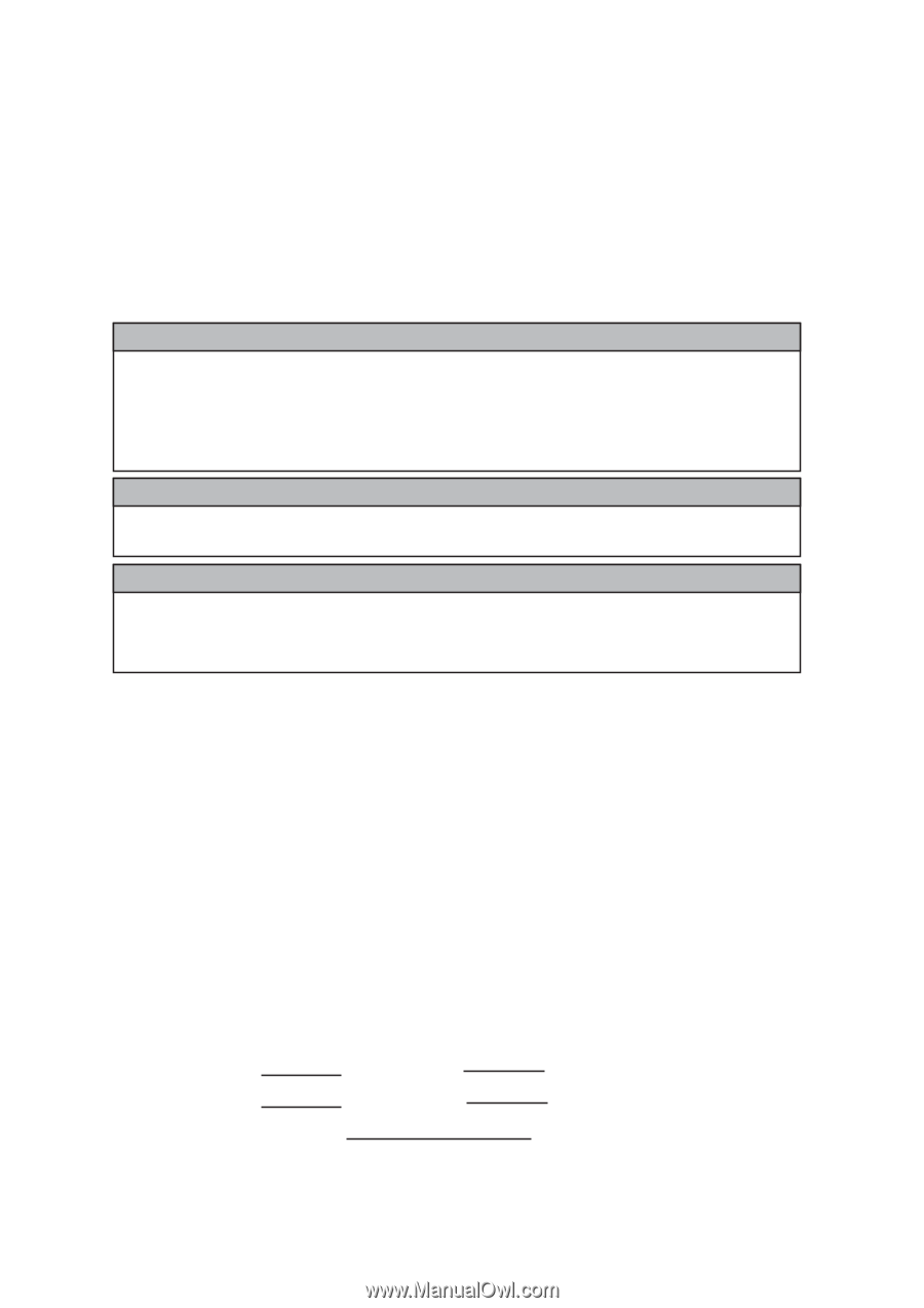
MODEL #
HB
M20
HB
MODEL #
HB
V20
HB
INSTALLATION DATE
The information contained in this booklet is subject to change without notice.
No.
0010578632A
M22
V22