Haier HSU-18HEK03 User Manual
Haier HSU-18HEK03 Manual
 |
View all Haier HSU-18HEK03 manuals
Add to My Manuals
Save this manual to your list of manuals |
Haier HSU-18HEK03 manual content summary:
- Haier HSU-18HEK03 | User Manual - Page 1
Manual of Room Air Conditioner Read this manual before installation Explain sufficiently the operating means to the user according to this manual. Drain-elbow 1 8 Cover 1 9 Cushion 4 10 1 Pipe supporting plate 11 Connecting cable 1 Arrangement of piping directions Rear left Left Rear - Haier HSU-18HEK03 | User Manual - Page 2
HSU-24HEK03 HSU-24LEK13 B= 60mm A=145mm 30mm 30mm 30mm HSU-12LEK13-M HSU-09LEK13 HSU-09LEK03 HSU-12LEK13 HSU-12LEK03 HSU-07LEK03 HSU-09HEK03 HSU-07HEK03 HSU-12HEK03 HSU-09LEK03/(DB) HSU-108CH09 HSU-12LEK03/(DB) HSU-138CH09 A=145mm B= 60mm HSU-18HEK03 HSU-18LEK13 HSU-18LEK03/(DB - Haier HSU-18HEK03 | User Manual - Page 3
service HSU-12LEK03/(DB) HSU-138CH09 connecting wiring: 3G1.5mm +1X0.75mm Power cable: 3G1.0mm 3G1.0mm Indoor unit Outdoor unit HSU-12LEK13-M 34 Power cable: 3G1.5mm 3G2.0mm Indoor unit HSU-18LEK13 Outdoor unit 1 Indoor unit HSU-12HEK03 HSU-07HEK03 Outdoor unit HSU-09HEK03 HSU-18HEK03 - Haier HSU-18HEK03 | User Manual - Page 4
Liquid side 6.35mm(1/4") Liquid side 9.52mm(3/8") Gas side 9.52mm(3/8") Gas side 12.7mm(1/2") Gas side 15.88mm(5/8") 18N.m 40N.m 40N.m 50N.m 60N.m 2. figure. (Note: Only for heat pump unit.) 3.Purging Method: Push the air out of the indoor unit and piping as followes: Tighten the caps on the
-
 1
1 -
 2
2 -
 3
3 -
 4
4
 |
 |
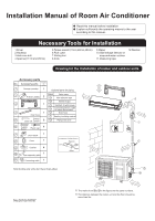
Installation Manual of Room Air Conditioner
No.0010518787
Read this manual before installation
1.Driver
2.Hacksaw
3.Hole core drill
4.Spanner(17,19 and 26mm)
5.Torque wrench(17mm,22mm,26mm)
6.Pipe cutter
7.Flaring tool
8.Knife
9.Nipper
12.Reamer
10.Gas leakage detector or
soap-and-water solution
11.Measuring tape
Explain sufficiently the operating means to the user
according to this manual.
A
B
C
D
E
F
G
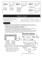
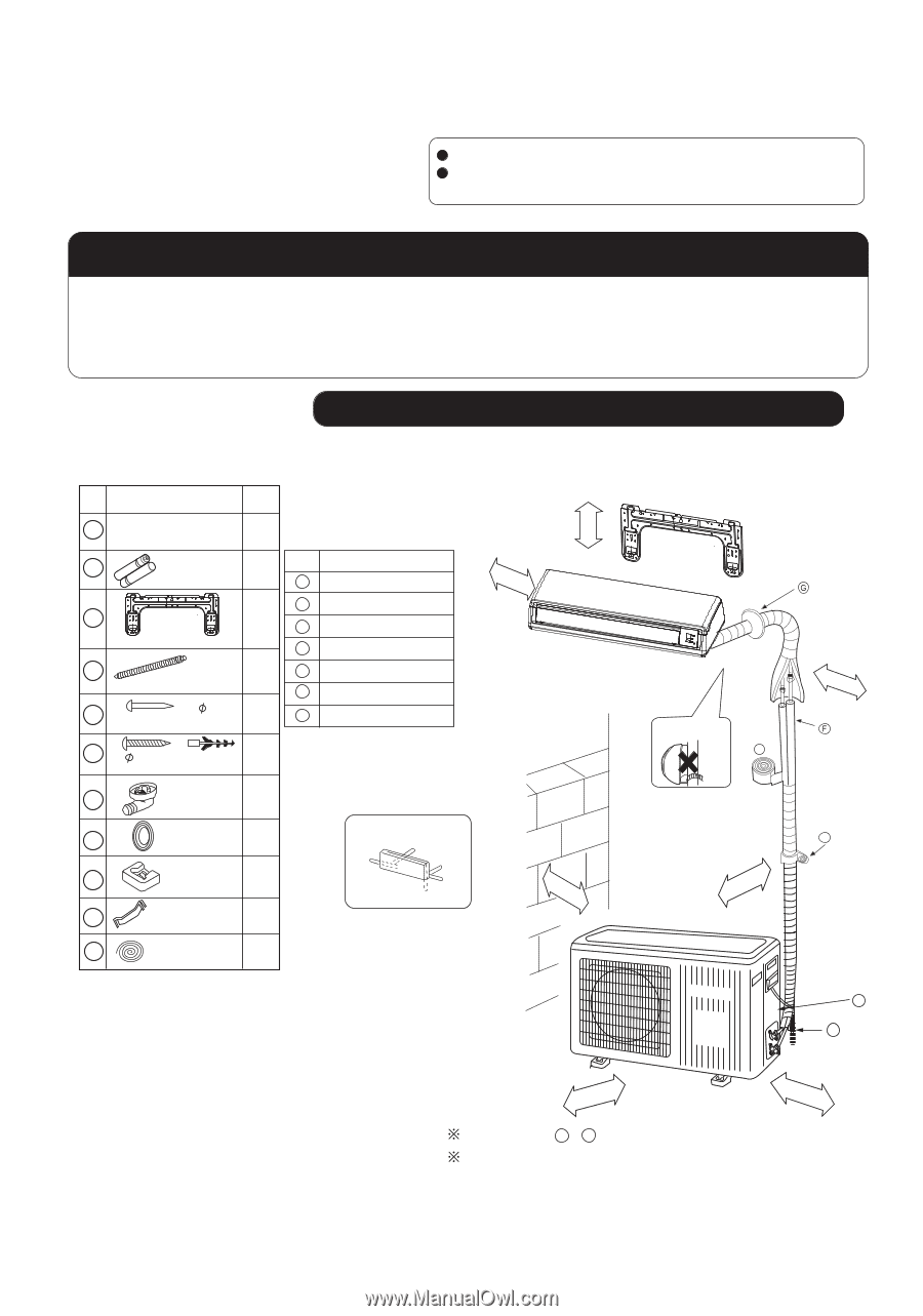
Optional parts for piping
Mark
Parts name
Non-adhesive tape
Adhesive tape
Saddle(L.S) with screws
Connecting electric cable
for indoor and outdoor
Drain hose
Heating insulating material
Piping hole cover
Arrangement of piping directions
Rear left
Rear
right
Left
Below
Right
The marks from
to
in the figure are the parts numbers.
The distance between the indoor unit and the floor should be
more than 2m.
A
G
Attention must be paid to
the rising up of drain hose
m
c
5
n
a
h
t
e
r
o
m
m
c
0
1
n
a
h
t
e
r
o
m
m
c
0
1
n
a
h
t
e
r
o
m
A
C
No.
Accessory parts
Remote controller
R-03 dry battery
Mounting plate
Drain hose
Steel nail, cement
Screw
Plastic cap
Drain-elbow
Cover
Cushion
1
1
2
3
4
5
6
7
8
9
10
2
1
1
6
4
1
1
4
1
Number
of
articles
Accessory parts
4X50
4X25
Pipe supporting plate
11
Connecting cable
1
m
c
0
1
n
a
h
t
e
r
o
m
m
c
0
6
n
a
h
t
e
r
o
m
m
c
5
1
n
a
h
t
e
r
o
m
m
c
0
1
n
a
h
t
e
r
o
m
D
E
Note:Cooling only units don't have Drain-elbow
Drawing for the installation of indoor and outdoor units
Necessary Tools for Installation