Haier HSU12XCK User Manual
Haier HSU12XCK Manual
 |
View all Haier HSU12XCK manuals
Add to My Manuals
Save this manual to your list of manuals |
Haier HSU12XCK manual content summary:
- Haier HSU12XCK | User Manual - Page 1
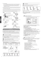
Manual of Room Air Conditioner models adopt HC FC free refrigerant R410A more than 10cm (3 7/8) more than 10cm (3 7/8) Attention must be paid to the pitch of drain hose G Optional parts to wall surface, roof or rooftop, fix a supporter securely with nails or wires in consideration of earthquake and - Haier HSU12XCK | User Manual - Page 2
them. 3. Coat the flaring seal face with refrigerant oil and connect pipes. Cover the connection part with heat insulation materials, cover with adhesive tape. Pipe supporting plate Fix with adhesive tape ƽ Indoor/outdoor electric cable and drain hose must be bound with refrigerant piping with - Haier HSU12XCK | User Manual - Page 3
2wire with ground 12AWG All models: Control cable: 4wire, 18AWG Indoor unit Outdoor unit HSU09XCK-W Power cable: HSU12XCK-W Power cable: 2wire refrigerant must be conducted by professional air conditioner servicer. Before adding additional refrigerant, perform air purging from the refrigerant - Haier HSU12XCK | User Manual - Page 4
valve Step 7. 2-way valve 3-way valve Service port cap Valve rod cap Valve rod cap CAUTION ƽ If the refrigerant of the air conditioner leaks, it is necessary to discharge all the refrigerant. Vacuum first, then charge the liquid refrigerant into air conditioner according to the amount marked on - Haier HSU12XCK | User Manual - Page 5
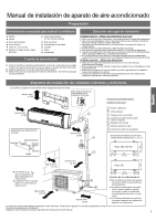
Manual de instalación de aparato de aire acondicionado Preparación Herramientas necesarias para realizar la drenaje sencillo y en el que puedan conectarse los tubos a la unidad exterior. ● Donde el aire frío pueda distribuirse uniformemente por la sala. ● Que esté cerca de una toma de suministro - Haier HSU12XCK | User Manual - Page 6
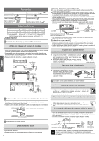
entubación por el lado izquierdo, corte con una cuchilla la cubierta de la entubación izquierda. En caso de realizar la entubación a través de la parte trasera izquierda, doble los tubos de acuerdo con la dirección de entubación que figura en la marca del orificio de entubación trasera izquierda - Haier HSU12XCK | User Manual - Page 7
un ingeniero profesional en aire acondicionado. Antes de añadir refrigerante adicional, realice una purga de aire desde los tubos refrigerantes ) HSU09XCK-W Cable de alimentación: ı 2 hilos con toma de tierra 16 AWG HSU12XCK-W Cable de alimentación: ı 2 hilos con toma de tierra 16 AWG 1. Si - Haier HSU12XCK | User Manual - Page 8
refrigeración (excepto el especificado, R410A) o aire en el sistema de circulación del refrigerante. Si carga del producto (por ejemplo, sobre la parte interna de la cubierta de la válvula de cliente cómo utilizar el aparato utilizando el manual de instrucciones. Compruebe los siguientes puntos de - Haier HSU12XCK | User Manual - Page 9
● Facilement vidangeable avec la tuyauterie connectée à l'unité extérieure. ● Où l'air froid puisse être réparti dans toute la pièce. ● Près d'une prise de doit être installée sur un mur, un toit ou la toiture, fixez un support avec des clous ou des fils en tenant compte des séismes et vents forts. ● - Haier HSU12XCK | User Manual - Page 10
thermique Tuyau de vidange Couvercle pour tuyauterie de gauche Tuyauterie Plaque de support de tuyau Fixez avec du ruban adhésif ● Le câble du ruban adhésif. 10 Ecrou de blocage Faisceau de câbles de l'unité Support de conduit Effectuez les 6 entailles Lors de la connexion du câble, confirmez - Haier HSU12XCK | User Manual - Page 11
un professionnel de la climatisation. Avant d'ajouter du réfrigérant, purgez l'air des tuyaux de réfrigération et de l'unité intérieure avec à 20 g/m. Unité intérieure Unité extérieure HSU09XCK-W Câble d'alimentation HSU12XCK-W Câble d'alimentation 2 fils avec terre, 16 AWG 2 fils avec terre, - Haier HSU12XCK | User Manual - Page 12
réfrigérant du climatiseur fuit, il faut vidanger tout le réfrigérant. Mettez d'abord sous vide, puis chargez le réfrigérant liquide dans le climatiseur d'air jusqu'à la quantité indiquée sur la plaque signalétique. ● Ne laissez pas les autres moyens de réfrigération, sauf pour celui spécifié (R410A
-
 1
1 -
 2
2 -
 3
3 -
 4
4 -
 5
5 -
 6
6 -
 7
7 -
8
-
9
-
10
-
11
-
12
 |
 |

Drawing for the installation of indoor and outdoor units
Necessary Tools for Installation
Hammer
Torque wrench
(17mm,22mm,26mm)
Nipper
Reamer
Hacksaw
Pipe cutter
Gas leakage detector or
soap-and-water solution
Hole core drill
Flaring tool
Spanner(17,19 and 26mm)
Knife
Measuring tape
Place where the distance of more than lm from televisions, radios, wireless apparatuses
and fluorescent lamps can be left.
In the case of fixing the remote controller on a wall, place where the indoor unit can
receive signals when the fluorescent lamps in the room are in use.
A distance marked
±
is available as illustrated in the below
figure.
Before inserting power plug into receptacle, check the voltage without fail.
The power source is the same as the corresponding name plate.
Install an exclusive branch circuit of the power.
A receptacle shall be set up in a distance where the power cable can be
reached.Do not extend the cable by cutting it.
Selection of Installation Place
Power
Source
Preparation
NO.00105
36242
Installation Manual of Room Air Conditioner
F
A
C
E
D
Optional parts for piping
Non-adhesive tape
Adhesive tape
Saddle (L.S) with screws
Connecting electric cable
for indoor and outdoor
Drain hose
Heating insulating material
Piping hole cover
Floor fixing dimensions of the
outdoor unit
Fixing of outdoor unit
Fix the unit to concrete or block
with bolts (10mm) and nuts firmly
and horizontally.
When fitting the unit to wall
surface, roof or rooftop, fix
a supporter securely with nails
or wires in consideration of
earthquake and strong wind.
If vibration may affect the
house, fix the unit by attaching a
vibration-proof mat.
The marks from
to
in the figure are the
parts numbers.
The distance between
the indoor unit and the
floor should be more
than 2m.
The models adopt HCFC free refrigerant R410A
more than
10cm (3 7/8)
more than 10cm
(3 7/8)
more than 10cm
(3 7/8)
more than 20cm
(7 7/8)
more than 15cm
(5 7/8)
more than 25cm
(9 7/8)
more than 60cm
(23 5/8)
A
G
A
F
C
E
D
G
B
Arrangement of piping
directions
Rear left
Left
Rear
right
Right
Below
G
Attention must be paid to
the pitch of drain hose
The above picture is for your reference only. Your product may look different.
Read this manual before installation.
Explain the operation of the unit to the user according to this manual.
Indoor Unit - Select a location that is
Outdoor Unit - Select a location that is
Robust not causing vibration, where the body can be supported sufficiently.
Not affected by heat or steam generated in the vicinity, where inlet and outlet of the
unit are not disturbed.
Possible to drain easily, where piping can be connected with the outdoor unit.
Where cold air can be spread in a room evenly.
Nearby a power receptacle. (Refer to drawings).
Less affected by rain or direct sunlight and is sufficiently ventilated.
Strong enough to bear the unit, where vibration and noise are not increased.
(4 1/2)
For:24k
Not causing a nuisance to neighbors due to discharged air or noise.
(10 1/16)
(5 1/2)
(19 2/3)
(5 1/2)
(24 7/8)
(4 1/2)
(13 1/2)
140
500
140
256
113.5
113.5
633
340
For:09k 12k 18k
(Unit:mm /
inch)