Harman Kardon A310 Owners Manual - Page 2
Kspecifications
 |
View all Harman Kardon A310 manuals
Add to My Manuals
Save this manual to your list of manuals |
Page 2 highlights
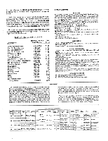
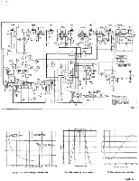
by reversing one or all of the AC power plugs. Simply reverse one at a time until improvement is experienced. Due to the conservative design and high quality components of the Theme, no routine maintenance other than yearly tube-testing is required. Should trouble develop, however, only the most qualified serviceman should be employed, as special equipment and training is required to properly service high fidelity equipment. This instruction booklet contains diagrams and other information needed by your repairman. It should be kept available for his use. LIST OF REPLACEABLE PARTS Description Harman- Kardon List Part Number Price Power Transformer FM IF Transformer FM Discriminator AM IF Transformer K Tran Coil Clip AM Osc. Coil Gang Condenser AM Antenna Loopstick Electrolytic Cap. 20,20/250 RF Trimmer 1-10 MMF Function Switch Dial Glass Dial Glass Clip Pointer Display Panel Escutcheon Cage Knob Instruction Sheet Tuning Meter FT481054 GT24605 GT24608 GT24610 Z24614 GL24610 JV24600 GL28827 JE28910 JV20688 ER481199 P481092 Z24774 Z24773 P28761 C28760 C28803 P20778 Z481200 7.50 1.50 2.10 1.30 .05 1.30 9.00 3.50 2.20 .30 2.50 1.25 .05 .30 4.75 6.75 7.50 .15 . 75 9.00 SPECIFICATIONS Rf SECTION Circuits: FM: Armstrong Circuit with Dual Limiters (Double Tuned) and FosterSeeley Discriminator. Automatic Frequency Control. Low noise, all triode front end with grounded grid RF amplifier and triode mixer. AM: Superheterodyne with tuned RF stage, and ferrite loop antenna. Two IF stages. 10 KC whistle filter. AVC operative over three stages. Sensitivity: FM: 1.8 microvolts for 30 db quieting; 1.2 microvolts for 20 db quieting. AM: Terminal Sensitivity: 3 microvolts. Loop Sensitivity: 15 microvolts/meter. Selectivity: FM: 200 KC bandwidth: 6 db down. AM: 10 KC bandwidth: 6 dh down. FM Discriminator peak to peak separation: 375 KC. Frequency Range: FM: 88-108 MC AM:530.1650 KC. FM Drift: ± 212/ KC with AFC on; .4- 20 KC with AFC oil. Image Rejection: FM: 50 db. AM: 50 db. IF Rejection: FM: 70 db. AM: 50 db. Antenna Input: FM: 300 ohms AM: Built-in low noise ferrite loopstick plus high impedance terminal for external antenna. Distortion: Less than 1% harmonic on FM. Lees than 1% harmonic for up to 80% mod. on AM. Frequency Response: FM: dh 20 to 20,000 c.p.s. including standard 75 micro- second deemphasis. AM: 3 db 20 to 5,000 c.p.s. Hum Level: 65 db below 100% modulation. AUDIO SECTION Circuits: Cathode Follower Output Output Level: FM: 2,/, volts for 100% modulation; 1 volt for 30% modulation. AM: 1 volt (average). Output Impedance: Low Impedance Cathode Follower OVERALL SPECIFICATIONS Controls: (Total 2) Function (OFF-AM-FM with AFC -FM without AFC) and Tuning Tube Complement: (Total: 12) 1-6AN4, 1-12AT7, 1-6AB4, 1-6BE6, 3.6BA6, 1.6AL5, 2.6AU6, 1-12AU7, 1.6X4. Dimensions: 1212/ " wide x 4" high x 8%" deep (including ferrite loopstick-not including knobs). Power Consumption: 50 watts Shipping Weight: 14 lbs. Finish: Chassis, escutcheon and cage: brushed copper-Display panel for escutcheon and knobs: matte black-Edge lighted dial glass: yellow and white. Hardware and Accessory Material Furnished: Mounting screws, template, FM antenna wire, instruction booklet, shielded output cable. Functional Features: (a) Counterweighted Tuning Control; (b) AFC defeat available on function switch. (c) Illuminated Tuning Meter; (d) Cathode follower output to drive tape recorder. Special Notes: (a) Can be stacked with C-300 amplifier in total height of 8", with C-100 amplifier in total height of 7%"; (b) Face up mounting of Theme permissible without special precaution. OPTIONAL ACCESSORIES (a) Brass finished escutcheon available on special order. (b) Brass finished cage available on special order. (c) Vertically calibrated dial glass available on special order. WARRANTY We warrant each Theme, Model A-310 to be free from de- fects in material and workmanship under normal use and serv- ice, and in accordance with the conditions herein below set forth, for a period of 90 days from date of delivery to the orig- inal purchaser, and agree to replace or repair any part or parts returned to us within said 90 days, with transportation prepaid, and which our examination shall disclose to our sat- isfaction to have been thus defective. This warranty does not include free labor, nor is it applicable to any instrument which shall have been repaired or altered in any way so as in our judgment to affect its stability or reliability nor which has been subject to neglect, misuse, abuse, negligence or accident nor which has had the serial number altered, effaced, or removed. Neither shall this warranty apply to any instrument which has been connected otherwise than in accordance with the instructions furnished by us. This warranty is expressly in lieu of all other warranties, express or implied, and of all other obligations or liabilities on our part, and we neither assume nor authorize any representative or other person to assume for us any other li ability in connection with the sale of the Model A-310 Theme. A-910 ALIGNMENT PROCEDURE FSw..i.tcth. Signal Generator Setting Freq. Mod. signal Input point cots, Indicator Connect Indicator seDttiianlg To: Adjust Output Indication Funct. Signal Generator Switch Setting Freq. Mod. St ignal Popi nat ontynt Connect Indicator ITnod:icator sDeitatinl g Adjust Output Indication Alf 455KC 30%Alf 6sE6 pi n 7 AC-VTVM Output or Scope Terminal - SAN IF Transformers Max. Output (T7, TO) 300KC FM 6AB4 FM 10.7MC 60 cycles Ping AC-VTVM "A" on or Schematic - scope thru 10011 4 FM IF Transformers (T1, Ti, Ti, T4) Max. gain and symmetry AM 1500KC 30%Alf AM Ant AC-VTVM Output Terminals or scope Terminal "' MC OSC, RF and TAnritmenmnaers Max. Output AM an, AM Mt AC- VTVIA Output anotrc MMKC 3°%"'" Terminals or scope Terminal '""'''' OSC Cull Max. Output n. a,... 300KC FM OAB4 FM 10"'"'" 60 Cycles Pin 0 FM 10.7MC 300KC FM 6AB4 60 Cycles pin 0 AC- VTVII "B" on or scope Schematic - AC-VIVM n or scope "''" - Limiter Transformer Max. gain (T5) Discriminator S Pattern of Max. Transformer gain and symm. FM 106MC 300KC FM FM Ant. 60 Cycles Terminals AC- VTVM or scope "A" ton., c, OSC, R and "."" Ant. Trimmer M''''ax. Output AM 600KC 30%All AM Ant Terminals AC-VTVM Output or scope Terminal 600KC AM, RF Coil Max. Output FM 90MC 63000KCcleFr I. oArCs- rcrpeM ..A.. Terminals 00MC °MSCC TSriFmarnder 11"' Output
-
 1
1 -
 2
2 -
 3
3 -
 4
4
 |
 |
