Harman Kardon A400 Owners Manual - Page 3
Replaceable, Parts
 |
View all Harman Kardon A400 manuals
Add to My Manuals
Save this manual to your list of manuals |
Page 3 highlights
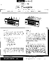
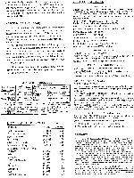
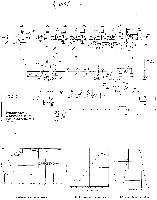
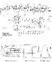
Now tune slowly through both stations, from the direction of the strong station. If the AFC control is set too high, the stronger station may be held until the tuning is past the weak station. Adjust the AFC so that when the stronger station pops out, the weaker station appears. MAINTENANCE AND REPAIR: In some installations, hum may be encountered due to a voltage difference between the amplifier, tuner arxl record changer chassis. This may be eliminated by reversing one or all of the AC power plugs. Simply reverse one at a time until improvement is experienced. Due to the conservative design and high quality components of the Counterpoint, no routine maintenance other than yearly tube-testing is required. Should trouble develop, however, only the most qualified serviceman should be employed, as special equipment and training is required to properly service high fidelity equipment. This instruction booklet contains diagrams and other information needed by your repairman. It should be kept available for his use. ALIGNMENT PROCEDURE Signal Generator Freq. Mod. 10.7MC 300KC FM 60 Cycles 10.7MC 300KC FM 60 Cycles Signal Input Point Output Indicator Connect Indicator To: sDeitatinl g Adjust 6AU6 V2-Pin 1 AC-VTVM or scope .S.cKh.emonatic thru 100K - 3 FM IF Transformers T2,T3,T41 6AU6 AC-VTVM "B" on - V2-Pin 1 or scope Schematic Limiter (TTra5n) sformer Output Indication Max gain and symmetry Max. gain 10.7MC 300KC FM 60 Cycles 6AU6 AC-VTVM V2-Pin 1 or scope 300KC FM FM Ant. AC-VTVM IUMC 60 Cycles Terminals or scope 90MC 300KC FM FM Ant. 60 Cycles Terminals AC-VTVM or scope " B" "A" ,,A', - Di scriminator S Pattern of Mcor Transformer gain and symm 106MC OSC, RF and Ant. Max. Output 90MC OSC, RF and Ant. Trimmer Max. Output LIST CF REPLACEABLE Description Part No. FM IF Transformer FM Disc. Transformer Power Transformer RF Trimmer 40,40/150V Electrolytic Volume Control, 1Meg. AFC Control, 1 Meg. SPST Switch & Cover Meter Dial Glass Glass Retaining Clip Pointer Display Panel Escutcheon Knob Knob (with white line) GT 24605 GT 24608 FT 35986 JV 20688 JE 22637 RV 35996 RV 35931 Z 35942 P 35938 Z 35944 Z 24773 P 35930 P 35931 P 20778 P 351043 PARTS List Price 2.70 3.15 8.50 .30 1.95 1.25 2.50 9.00 L25 .05 .30 4.35 7.00 .15 .20 SPECIFICATIONS RF SECTION CIRCUITS: FM: Armstrong Circuit with Dual Limiters (Double Tuned). and Foster-Seeley Discriminator Automatic Frequency Control. Low noise front end with tuned RF stage and triode mixer. SENSITIVITY: FM: 3 microvolts for 30 db quieting; 2 microvolts for 20 db quieting. SELECTIVITY: FM: 200 KC bandwidth: 6 db down. FM Discriminator peak to peak separation: 375 KC. FREQUENCY RANGE: FM: 88.108 MC FM DRIFT: 0 12/ KC with AFC on; ±20 KC with AFC off IMAGE REJECTION: FM: 50 db. IF REJECTION: FM: 70 db. ANTENNA INPUT: FM: 300 ohms DISTORTION: Less than 1% harmonic FREQUENCY RESPONSE: ±12/ db 20-20,000 c.p.s. HUM LEVEL: 60 db below 100% modulation AUDIO SECTION CIRCUITS: Cathode Follower Output OUTPUT LEVEL: 3 volts for 100% modulation; 1 volt for 30% modulation (level set control permits 20 db reduction). OUTPUT IMPEDANCE: Low Impedance Cathode Follower OVERALL SPECIFICATIONS CONTROLS: (Total 2) Power/variable AFC and Tuning TUBE COMPLEMENT: (Total: 8) 1.6U8, 1- 12AT7, 4-6AU6, 1-6AL5, 1-12AU7, Selenium Rectifier. DIMENSIONS: 11-1/8" wide x 4" high x 712/ " deep (not including knobs). POWER CONSUMPTION: 35 watts SHIPPING WEIGHT: 8%2 lbs. FINISH: Chassis and escutcheon: brushed copper - Display panel for escutcheon and knobs: matt black - Edge lighted dial glass: yellow and white. ACCESSORY MATERIAL FURNISHED: FM antenna wire, instruction booklet, shielded output cable. FUNCTIONAL FEATURES: (a) Counterweighted Tuning Control; (b) Variable AFC control; (c) Output Level Control; (d)Illuminated Discriminator Balance Tuning Meter. SPECIAL NOTES: (a) Can be stacked with C-100 amplifier in total height of 734"; (b) Face up mounting of Counterpoint permissible without special precaution. OPTIONAL ACCESSORIES (a) Metal Cage (Model AC-4) finished in matching brushed copper, furnished with mounting hardware and instructions. (b) Brass finished escutcheon available on special order. (c) Brass finished cage available on special order. (d) Vertically calibrated dial glass available on special order. WARRANTY: We warrant each Counterpoint, Model A-400 to be free from defects in material and workmanship under normal use and service, and in accordance with the conditions herein below set forth, for a period of 90 days from date of delivery to the original purchaser, and agree to replace or repair any part or parts returned to us within said 90 days, with transportation prepaid, and which our examination shall disclose to our satisfaction to have been thus defective. This warranty does not include free labor, nor is it applicable to any instrument which shall have been repaired or altered in any way so .as in our judgment to affect its stability or reliability nor which has been subject to neglect, misuse, abuse, negligence or accident nor which has had the serial number altered, effaced, or removed. Neither shall this warranty apply to any instrument which has been connected otherwise than in accordance with the instructions furnished by us. This warranty is expressly in lieu of all other warranties, express or implied, and of all other obligations or liabilities on our part, and we neither assume nor authorize any representative or other person to assume for us any other liability in connection with the sale of the Model A-400 Counterpoint.
-
 1
1 -
 2
2 -
 3
3 -
 4
4 -
 5
5
 |
 |
