Harman Kardon AVR 335 Quick Start Guide - Page 3
Audio Connections, Connecting EzSet+ Microphone - owners manual
 |
View all Harman Kardon AVR 335 manuals
Add to My Manuals
Save this manual to your list of manuals |
Page 3 highlights
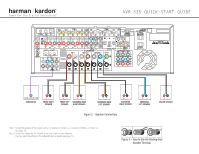
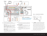
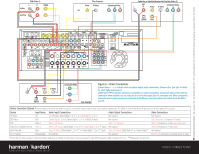
FM Antenna AM Antenna CD PLAYER L R Optical Coax Figure 5 - Connecting EzSet+ Microphone AUDIO RECORDER REC/IN PLAY/OUT Step 4. Connect AM and FM antennas (Fig. 4) (see page 14). Step 5. Connect source components, as shown in Figures 4 and 6, and the Device Connection Options chart on the back of this guide (see pages 14-15). AUDIO connections: Right channel (red) on source to right (red) on AVR, and left channel (white) on source to left (white) on AVR. DIGITAL AUDIO connections, if available: Choose either coax (orange) to coax (orange) OR optical to optical for each device. The Coax 1 input defaults to the DVD player, but may be reassigned. Assign the other digital inputs and outputs as appropriate for your equipment (see Step 7). VIDEO connections: Choose component (Y/Pb/Pr - green/blue/ red), composite (yellow) or S-video (4-pin) for each video source. Connect the component, composite and S-video Monitor outputs to your Video Monitor (TV). Switch your TV set's input to match the type of video used for the currently selected source. Figure 4 - Audio Connections Dashed lines (- - - -) indicate coax and optical digital audio connections. Choose either type (but not both) for each digital audio source. /EQ Step 6. Plug all components into AC power outlets. The outlets on the back of the AVR 335 should be used only for low-current products, such as CD or DVD players, and the total should not exceed 100 watts. Basic Receiver Configuration Step 7. Select digital inputs: If your DVD is connected to Coax 1, no adjust- ment is needed. For any other digital-device connections, use the front-panel Digital Select button and the arrow buttons to select an optical or coax digital input (see page 18). Step 8. Select a surround mode: Press the Surround Mode button on the front panel to select Dolby® Pro Logic® II - Movie. (You may select other modes later as you become familiar with the AVR 335; see pages 18-20.) /EQ Step 9. Use + to configure and optimize your system: Plug the EzSet+ microphone into the front-panel Headphones Jack (Fig. 5). Place the microphone at the center of the room, or at your normal listening position. If desired, the mike may be attached to a standard camera tripod using the threads on the bottom of the mike. Follow the instructions on pages 20-21 of the Owner's Manual, which contains the steps needed to activate the system. As EzSet+ senses the output of each speaker, you will hear loud test signals. This is a normal part of the EzSet+ process. When the on-screen menu indicates that setup is complete, your system is adjusted for output levels, delay times and speaker set- tings. Unplug the microphone and store it for future use. Step 11. Your system is configured - sit back and enjoy! SPEAKER AND AUDIO CONNECTIONS
-
 1
1 -
 2
2 -
 3
3 -
 4
4
 |
 |
