Harman Kardon AVR 630 Quick Start Guide - Page 3
Speaker And Audio Connections - watts per channel
 |
View all Harman Kardon AVR 630 manuals
Add to My Manuals
Save this manual to your list of manuals |
Page 3 highlights
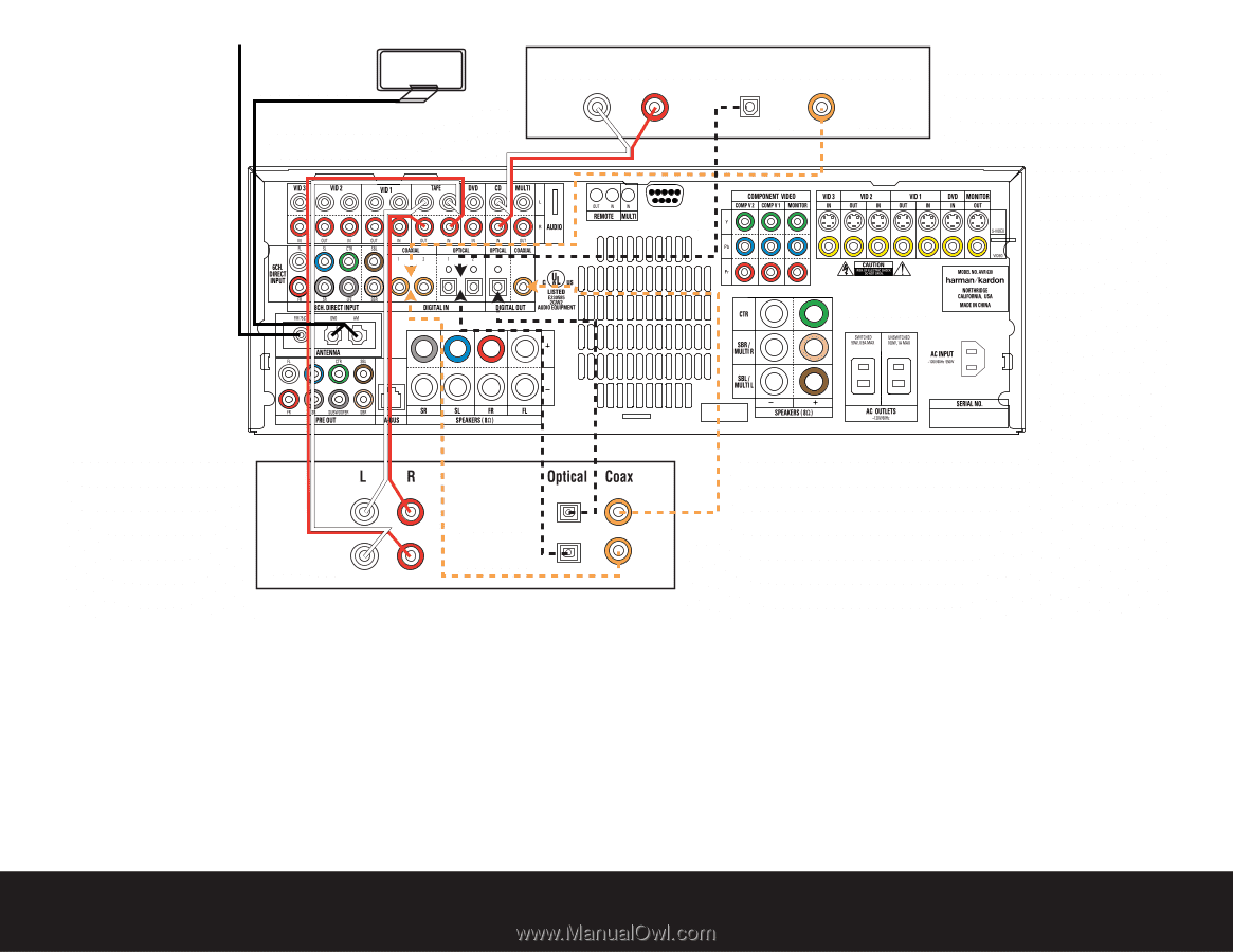
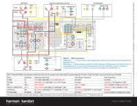
FM Antenna AM Antenna CD PLAYER L R Optical Coax REC/IN PLAY/OUT Figure 4 - Audio Connections Dashed lines (- - - -) indicate coaxial and optical digital audio connections. Choose either type (but not both) for each digital audio source. AUDIO RECORDER Step 4. Connect AM and FM antennas (Fig. 4) (see page 16). Step 5. Connect source components, as shown in Figures 4 and 5, and the Device Connection Options chart on the back of this guide (see pages 16-17). AUDIO connections: Right channel (red) on source to right (red) on AVR, and left channel (white) on source to left (white) on AVR. DIGITAL AUDIO connections, if available: Choose either coaxial (orange) to coaxial (orange) OR optical to optical for each device. The Coaxial 1 input defaults to the DVD player; however, it may be reassigned. Assign the other digital inputs and outputs as appropriate for your equipment (see Step 7). VIDEO connections: Choose component (Y/Pb/Pr - green/blue/ red), composite (yellow) or S-Video (4-pin) for each video source. The Component Video 1 inputs default to the DVD player, but may be reassigned. Connect the component, composite and S-Video Monitor outputs to your Video Monitor (TV). Switch your TV set's input to match the type of video used for the currently selected source. Step 6. Plug all components into AC power outlets. The outlets on the back of the AVR 630 should be used only for low-current products, such as CD or DVD players, and the total should not exceed 100 watts. Basic Receiver Configuration Step 7. Select digital inputs: If your DVD is connected to Coaxial 1, no adjustment is needed. For any other digital-device connections, use the front-panel Digital Select button and the arrow buttons to select an optical or coaxial digital input (see pages 21 and 32). Step 8. Configure speakers: No action is needed if you have five "small" satellite-type speakers and a subwoofer. Otherwise, press the Speaker button and then the Set and arrow buttons to select the correct speaker choices for your system (see pages 23-25). Step 9. Set the Output Levels with EzSet: Set the Volume to -15dB. Sit in the listening position and hold the remote in front of you at shoulder level, pointing it at the AVR. Press the EzSet button on the remote, and then the Set button when it lights red. Following the instructions in the remote's LCD display, press the button on the remote until the display shows the number of speakers in your system and then press the Set button again. Hold the remote steady until the LCD display flashes a COMPLETE message (see page 26). Step 10. Your system is configured - sit back and enjoy! SPEAKER AND AUDIO CONNECTIONS
-
 1
1 -
 2
2 -
 3
3 -
 4
4
 |
 |