Hayward 100K Btu Abg Or Spa H Propane Models: ABG1001 and H100ID1 - Page 3
I. General Information
 |
View all Hayward 100K Btu Abg Or Spa H Propane manuals
Add to My Manuals
Save this manual to your list of manuals |
Page 3 highlights
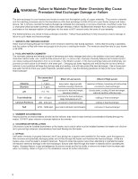
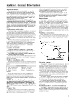
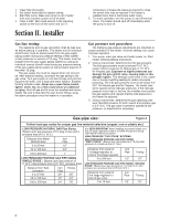
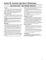
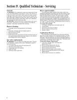
Section I. General Information Important notice: The instructions herein are intended for the use of a qualified technician, specifically trained and experienced in the installation of this type of heating equipment. Some states or provinces require that installation and service personnel performing the installation be licensed. If this is the case in the state or province where heater is located, the contractor must be properly licensed. WARNING: Failure to comply with the appliance installation instructions and service instructions in this manual may result in equipment damage, fire, asphyxiation, or carbon monoxide poisoning. Exposure to products of incomplete combustion (carbon monoxide) can cause cancer and birth defects or other reproductive harm. Conformance with codes: The heater shall be installed in accordance with all local and state codes. The heater installation must conform to the latest edition of the National Fuel Gas Code American National Standard (ANSI) Z223.1 and with the requirements of the authority having jurisdiction. Design Certification in the United States is in compliance with ANSI Z21.56 (latest edition). For Canadian installations, the heater must be installed in accordance with standards CAN/CGA B149.1 and B149.2 - INSTALLATION CODES FOR GAS BURNING APPLIANCES AND EQUIPMENT and/or local codes, and if applicable, Standard CSA C22.1 - CANADIAN ELECTRICAL CODE, Part 1. Location of heater: Locate the heater in an area where a leaking heat exchanger or connection leak will not result in damage to the area adjacent to the heater or structure. This heater must be installed at least five feet from the wall of an above-ground pool. The heater shall not be installed with the top of the vent assembly within 10 feet below or to either side of any opening into the building. Outdoor installation only: The following installation and service clearances must be maintained from surfaces to provide adequate air flow to the heater. Outdoor Installations Top - Unobstructed Front - 10 inches Back - 10 inches Right side - 10 inches Left side - 10 inches Bottom - Combustible floor Figure 1 An A.G.A. Certified main gas valve shutoff must be installed outside of the cabinet and within 6 feet of the heater. Gas shutoff valve must have an inside diameter large enough to supply the proper amount of gas volume to the heater. NOTE: Do not use flexible appliance connectors on any gas connections unless the connector is A.G.A. approved for outdoor Installation, Is marked with the BTUH capacity (which must be equal to or greater than 100,000 BTUH), and the type of gas (Natural or LP) to be used. Propane Gas: All Propane gas tanks must be located outdoors away from the pool and in accordance with the standard for storage and handling of propane gas, ANSI/NFPA 58 (latest edition) and applicable local codes. If propane gas tank is installed underground, the discharge of the regulator vent must be above the highest probable water level. Propane tanks must have sufficient capacity to provide adequate vaporization for the full capacity of the equipment at the lowest expected temperatures. Consult a propane company expert for correct sizing. Water piping: This heater is designed for use with pool and spa/hot tub water only, as furnished by municipal water distribution systems. The warranty does not cover heater use with mineral water, sea, salt, or other non-potable waters. Do not install any restriction in the water pipe between a heater outlet and the pool/spa with the exception of a threeway switching valve and associated check valve. Blockage of water flow from heater return to pool may result in fire or explosion causing property damage, personal injury, or loss of life. Plumbing connections: Water flow rate to the pool must be between 20 and 70 gpm. If flow rate exceeds 70 gpm an external by-pass valve must be installed. Figure 2 shows a typical heater installation. Electrical system: This heater is equipped with a standard 3-prong 120 volt cordset. The plug must be inserted into a GFI protected, watertight, outdoor receptacle rated for at least 10 amps. The heater must be electrically grounded and bonded in accordance with local codes, or in the absence of local codes, with the National Electrical Code ANSI/AFPA 70. If the heater must be hard wired, open the junction box and disconnect the cord. Remove the cord and strain relief and wire the heater in accordance with local codes or the National Electrical Code. The ignition system used to light the burners is a direct spark system which requires 120 volt AC current as does the blower motor. The system amp draw is 2 amps. It is strongly recommended that the heater be supplied with a constant power source. If remote operation is required, the heater should be controlled through the thermostat only. Installation above or below water level: This heater is supplied with a pressure switch factory set at 3.0 psi. If the heater does not operate and the pressure switch is at fault, the following procedure is recommended to adjust the switch: 3
-
 1
1 -
 2
2 -
 3
3 -
 4
4 -
 5
5 -
 6
6 -
 7
7 -
 8
8 -
 9
9 -
10
-
11
 |
 |
