Hayward Aqua Rite AQ-RT-PRO prior to Oct 08 - Page 19
Electrolytic Cell and Flow Switch - p kit
 |
View all Hayward Aqua Rite manuals
Add to My Manuals
Save this manual to your list of manuals |
Page 19 highlights
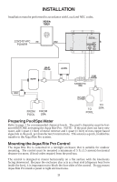
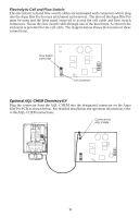
Electrolytic Cell and Flow Switch: The electrolytic cell and flow switch cables are terminated with connectors which plug into the Aqua Rite Pro for easy attachment and removal. The door of the Aqua Rite Pro must be open and the front panel removed to access the cell cable and flow switch connectors. Route the flow switch cable through one of the knockouts. A cutout in the enclosure is provided for the cell cable. The diagram below shows the location of these connections. Flow Switch Connector Cell Connector Optional AQL-CHEM Chemistry Kit Plug the connector from the AQL-CHEM into the designated connector on the Aqua Rite Pro PCB as shown below. For detailed installation and operation information, refer to the AQL-CHEM instructions. Connector for AQL-CHEM 16
-
 1
1 -
2
-
3
-
4
-
5
-
6
-
7
-
8
-
9
-
10
-
11
-
12
-
13
-
 14
14 -
 15
15 -
 16
16 -
 17
17 -
 18
18 -
 19
19 -
 20
20 -
 21
21 -
 22
22 -
 23
23 -
 24
24
 |
 |
