Hayward ColorLogic 2.5 Model: Series SP0521 - Page 3
Hayward ColorLogic 2.5 Manual
 |
View all Hayward ColorLogic 2.5 manuals
Add to My Manuals
Save this manual to your list of manuals |
Page 3 highlights
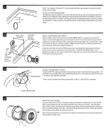
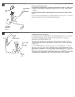
■ JUNCTION BOX TO JUNCTION BOX / (OPTIONAL) i fi Al /7 INSTALL FIELD-INSTALLED WIRING Run conduit from the junction box to the power supply, pool/spa controller, or switch box. Snake 3 wires (# 14 AWG or larger) through the conduit from the junction box to the power supply, pool/spa controller, or switch box. If multiple lights are being installed, run additional wires from the junction box to the additional junction box(es). Use wire nuts to connect the field-installed wiring to the light fixture cord in the junction box. Connect the ground wires to the ground terminal connections inside the junction box. ........... TO POWER SUPPLY & SWITCH TO POOL LIGHT SWITCH I ii It • POWER SUPPLY (LOAD CENTER) JUNCTION BOX TO JUNCTION BOX (OPTIONAL) rti I .// 'II I Ii h P. 0) / ......... TO POOL LIGHT CONNECTING THE LIGHT TO CONTROLS In accordance with N.E.C. Article 680-22, all 120V underwater light fixtures must have a GFCI protector. If multiple Hayward ColorLogic lights are installed, they may be synchronized. To enable light synchronization, wire all lights to the same switch. The Hayward ColorLogic lights are controlled via power-cycling. No special controller is required to activate the light and switch it through different modes. The light fixture can be switched with any basic on/off light switch. If a Hayward PSC2100 Pool/Spa Control System is being used, wire the LED light fixture to either the main "LIGHT" circuit, or the "AUX 4" circuit. The Hayward PSC2100 controller has an integral GFCI for these circuits and an additional GFCI need not be installed. Please note that if the "LIGHT" circuit on the PSC controller is used, the controller must be configured for a non-dimming light (dip switch #1 down). The Hayward LED light fixtures are also compatible with a variety of other pool/spa controllers that control devices through simple on/off switching; refer to your controller's installation manual for details.
-
 1
1 -
 2
2 -
 3
3 -
 4
4 -
 5
5 -
 6
6
 |
 |
