Hayward EcoStar Technical Guide
Hayward EcoStar Manual
 |
View all Hayward EcoStar manuals
Add to My Manuals
Save this manual to your list of manuals |
Hayward EcoStar manual content summary:
- Hayward EcoStar | Technical Guide - Page 1
Variable Speed Pump and Drive Technical Guide © 2011 Hayward Pool Products Version 2 Drive FW 1.02 Interface FW 2.55 residential Interface FW 1.00 commercial - Hayward EcoStar | Technical Guide - Page 2
Table of Contents Safety Precautions Installation Programming Operation Programming Scenarios Disassembly/Assembly Password/Commercial Diagnostics/Troubleshooting Page 1 Page 2-14 Page 15-29 Page 30-31 Page 32 Page 33-38 Page 39-40 Page 41-48 - Hayward EcoStar | Technical Guide - Page 3
receptacle. Before working on drive or motor, turn off power supply to the drive. Failure to bond drive to pool structure will increase risk for electrocution and could result in injury or death. To reduce the risk of electric shock, see installation instructions and consult a professional - Hayward EcoStar | Technical Guide - Page 4
of pipe (L) between pump suction port and first elbow or fitting should be at least 5 times pipe size. MAXIMUM RECOMMENDED SYSTEM FLOW RATE BY PIPE SIZE 1.5" 2" 2.5" 51gpm 8fps 84gpm 8fps 120gpm 8fps 38gpm 6fps 63gpm 6fps 89gpm 6fps * Refer to equipment manuals for flow rates. 3" 184gpm - Hayward EcoStar | Technical Guide - Page 5
Installation - Electrical Remove the electrical cover plate as shown below (fig 2, 3 & 4) Figure 2 Note: If power is removed from the pump, all settings will be protected for at least 5 years. Figure 3 Figure 4 Page 3 - Hayward EcoStar | Technical Guide - Page 6
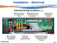
wiring locations (fig 5) Wiring connection for incoming motor wires Wiring plug for relay connected controls & stop switch Wiring plug for wall mounted interface Wire connection for incoming line voltage (230v) Channel for running low voltage data cable Wiring plug for data link with Hayward - Hayward EcoStar | Technical Guide - Page 7
230 VAC, 60Hz, Single Phase. 2. Breaker, wire size would be determined by the NEC and local code requirements. Ground Wire Terminal. It is below high voltage wires and should be connected first. Note: When connecting high voltage for an EcoStar that is data connected to a Hayward/Goldline control - Hayward EcoStar | Technical Guide - Page 8
Installation-Interface removal/positioning The interface assembly on the EcoStar can be configured in four different positions. 1. Remove the two screws as shown (fig 7). 2. Remove the interface assembly as shown (fig 8). 3. Reposition interface assembly as - Hayward EcoStar | Technical Guide - Page 9
EcoStar and includes blank cover, mounting bracket and new terminal block for connecting to the interface assembly. Maximum 500‟ for data cable used for wall mount or control connection. 2. After removal of the interface assembly (Page 7) remove the plug connecting the drive to the - Hayward EcoStar | Technical Guide - Page 10
opening (fig 15). 5. Remove the wall mounting data plug from the electrical compartment as shown (fig 16). 6. You will need to procure a six wire data cable, as short as possible, and attach the wires to the data plug as shown (fig 17) taking care to note the color and corresponding number next to - Hayward EcoStar | Technical Guide - Page 11
the bottom of the bracket (fig 18). 8. Attach the six wires to the new data plug as shown, taking care to note the color and corresponding number on the data plug as you did with the data plug on the pump (fig 20). Install the plug into the interface assembly (fig 19). 9. Attach - Hayward EcoStar | Technical Guide - Page 12
pump to 3 on the controller and 1 on the pump to 4 to the controller as shown (fig 22 & 23). Reinstall plugs. Wire colors can be different as those shown as long as they match point to point. Note: When connecting high voltage for an EcoStar that is data connected to a Hayward/Goldline control - Hayward EcoStar | Technical Guide - Page 13
controls) 1. Pump power (230 VAC) needs to be brought into the "line in" contacts on the Filter Pump Relay from a breaker in the control box. The "Load Out" side will feed the incoming high voltage for the pump (fig 24). Cable used for data connections should be rated for maximum voltage in motor - Hayward EcoStar | Technical Guide - Page 14
-Relay Connected Controls (Non Hayward/Goldline compatible software & third party controls) 2. 1, 3 and 5 from the pump terminal needs to be wired to the Load side of 4. The other leg of the 24 VAC connection on each control relays as shown (fig 25). the pump terminal needs to be wired to the - Hayward EcoStar | Technical Guide - Page 15
Non Hayward/Goldline compatible software & third party controls) 5. By using a sequence of off and on, timer speeds can be controlled. As shown by the charts, the number of speeds available depends on the number of aux relays used. Filter pump relay plus 3 aux relays allows control of eight speeds - Hayward EcoStar | Technical Guide - Page 16
a latching style that is normally open (NO). Some switches have wiring for both NO and NC (normally Closed). Refer to the e-switch for its internal wiring. When the switch is pressed the 24v circuit is completed and the pump will shut down operation. Remote stop switch purchased separately Fig 29 - Hayward EcoStar | Technical Guide - Page 17
solid when there is an error condition. It will blink when in the quick clean mode with the SVRS models. TIMERS ACTIVE LED LED will illuminate once the timers have been programmed., even if the pump is not running. QUICK CLEAN Elevates the speed of the pump to max set speed for cleaning. Places SVRS - Hayward EcoStar | Technical Guide - Page 18
Programming 1. When power is supplied to the pump, the pump model will display, then the following screens (fig 31 & 32). Timer 1 will have default setting of 1750 RPM (50%), 7 days a week from 12:00 am - 11:45 pm. 2. Since timer 1 has a factory default setting the pump will come on and run until - Hayward EcoStar | Technical Guide - Page 19
Programming-Configuration 4. On the next screen you will be asked to press the button to enter the Configuration Menu (fig 34). 5. On the next screen it will tell you how to use the & buttons to adjust, and the to go to the next item (fig 35). Press the button to continue. Fig 34 Fig 35 Page 17 - Hayward EcoStar | Technical Guide - Page 20
Programming-Configuration 6. This screen allows you to change the day and time by pressing the to access or skip by pressing the button (fig 36). button 7. You now Use the button to highlight the day, hour, minute and AM/PM. Use the & buttons to change (fig 37). After setting the AM/PM press - Hayward EcoStar | Technical Guide - Page 21
Programming-Configuration 8. You now select the speed indicator for RPM (revolutions per minute) or % of full speed (100% equals 3450 RPM) by pressing the & buttons (fig 38 & 39). The setting you select will be used throughout programming. Press the button to continue. Fig 38 Fig 39 Page 19 - Hayward EcoStar | Technical Guide - Page 22
allowed flow for pipe. SVRS model will not go lower than 1000 rpm (29%) Press the button to continue. 10. You will now see the MIN allowed speed. Same as #10 above for setting speed (fig 41). Press the button to continue. Note: When hooked up to a Hayward/Goldline compatible software controls place - Hayward EcoStar | Technical Guide - Page 23
Programming-Configuration 11. You will now see the max-speed Prime period. Press & buttons for Auto Sense (3000 RPM), or a 3 min (max set speed) prime period (fig 42).This function only works in Standalone and Relay Control modes. Press the button to continue. 12. You will now see the Remote - Hayward EcoStar | Technical Guide - Page 24
Programming-Configuration Hayward/Goldline Compatible Software Control 13. For EcoStar interface software v2.51 data linked to a Goldline/Hayward compatible software control pressing & buttons will give you 9 address choices. The Goldline/Hayward controller will only recognize address 1 (Pool - Hayward EcoStar | Technical Guide - Page 25
is Disabled) by pressing the & buttons.(fig 46). Enabling this feature will turn on the EcoStar, if stopped, to protect the drive . Press the button to continue. 16. If the Low Temp Operation is enabled you will be asked to set the Low Temp Speed ( fig 47). The default is 1000 rpm (29%). This - Hayward EcoStar | Technical Guide - Page 26
, press the button to continue (fig 50). 19. If the Relay Control or the Stand alone feature is being used the timer menus would be the next to program. There will be a screen telling you to use the timers mode to set or change time clock perimeters. Press the button to continue. Fig 49 - Hayward EcoStar | Technical Guide - Page 27
Programming-Timers Stand alone/Hayward Stand alone: Both times and speeds need to be set. Compatible Software controller: No timer or speed settings necessary. Com bus address needs to be set. Relay Control Only requires that speed be set as relays on controller will start and stop pump. Note - Hayward EcoStar | Technical Guide - Page 28
Programming-Timers 3. This screen (fig 53) will alternate with fig 49 on the previous page. This screen tells you to use the button to modify the timer setting (fig 54). Press the button to continue. 5. This screen will allow you to adjust the speed setting from 600 RPM (17%) to 3450 RPM (100%) by - Hayward EcoStar | Technical Guide - Page 29
57 Note: There are 8 timers available. The lower numbered timer will be the most dominate. If setting one timer to cover low speed for overall time period, make it timer #8 as it is the least dominate. Setting the start and stop time the same will disable that timer and show that it is off. Page - Hayward EcoStar | Technical Guide - Page 30
Programming - Speeds 1-4 1. Press the button until Speeds Menu appears (fig 58). There are four (4) Speed buttons that can be set. Press the button to enter Speeds Menu. 2. Pressing the & buttons allows you to select a variety of names to apply to this Speed button (fig 59). Press the button to - Hayward EcoStar | Technical Guide - Page 31
can now set Speed 2, 3 & 4 following the directions for Speed 1. After Speed 4 is set press the button to continue. Note: Refer to page 30 for instructions on speed changing while operating speeds. Fig 61 If at any time during settings for any menu item you press the menu button, you will be asked - Hayward EcoStar | Technical Guide - Page 32
to the speed selected or timed. Auto Prime and the 3 minute prime only works in the stand alone mode. In Auto Prime, pump will show "Prime Failed" if prime is not achieved within 15 minutes. 4. The consumption in watts will show on the display while the pump is running. 5. If the EcoStar you are - Hayward EcoStar | Technical Guide - Page 33
when there is an error condition. It will blink when in the quick clean mode with the SVRS models. TIMERS ACTIVE LED LED will illuminate once the timers have been programmed. Even if the pump is not running. QUICK CLEAN Elevates the speed of the pump to the maximum set speed for cleaning. Disables - Hayward EcoStar | Technical Guide - Page 34
Programming Scenarios Below is one possible Stand Alone scenario. Timer 8: Pump comes on at 6 am and goes off at 5:45 am Set to run the entire timing sequence at the low speed setting. 6 am The lower the timer number the higher the priority. In other words, timer 1 will override timer 8 settings - Hayward EcoStar | Technical Guide - Page 35
/Assembly This guide will only cover the disassembly of the drive and motor area for this guide. The wet end disassembly of the EcoStar is exactly like the standard TriStar pump. Wiring Compartment Cover Interface Assembly Variable Speed Drive Figure 63 Motor/Fan Shroud Motor Page 33 - Hayward EcoStar | Technical Guide - Page 36
Disassembly/Assembly 1. Shut down power to the pump by moving the breaker supplying power to the pump to the off position. 2. Remove the screw as shown (fig 64). Remove the wiring compartment cover as shown (fig 65). Figure 64 Figure 65 Page 34 - Hayward EcoStar | Technical Guide - Page 37
Disassembly/Assembly 3. Remove the two screw as shown (fig 66). 4. Remove the interface assembly from the Motor drive (fig 67). 5. Remove the plug as shown (fig 68) and place the interface assembly aside. Figure 66 Figure 67 Figure 68 Page 35 - Hayward EcoStar | Technical Guide - Page 38
as shown (fig 69 & 70). Make sure during reassembly to tighten these screws fully as they act as the ground between the drive and the motor. 7. Pull the three wire connectors off the spade terminals as shown. Note the color designation for each spade when reassembling (fig 71 & 72). Figure 69 - Hayward EcoStar | Technical Guide - Page 39
is called the heatsink (fig 73 & 74). During reassembly make sure all three wires are pulled completely through the hole provided to prevent pinching between the motor and the drive. 10. The drive assembly is one sealed unit and cannot be disassembled. It is replaced as an assembly. Make sure any - Hayward EcoStar | Technical Guide - Page 40
shroud as shown (fig 75). 12. Remove the fan Shroud as shown (fig 76). Note: The fan shown (fig 73) comes as part of the motor assembly. It should also be noted that the fan shroud can be installed upside down. Square top section of shroud should always be on the - Hayward EcoStar | Technical Guide - Page 41
Commercial 1. If you have a commercial EcoStar you will see this screen (fig 77) after Low Temp Operation. At this point you can enable or disable the Password Protection feature by pressing the & button. Press the button to continue. 2. At this point (fig 78) you can set the Password Timeout in 15 - Hayward EcoStar | Technical Guide - Page 42
4. If you selected to change the password you will see this screen (fig 80) to set the password and the next screen (fig 81) reset to factory default by pressing and holding the speed 1 and 4 buttons at the same time while powering on the pump, or by resetting all parameters in the Configuration menu - Hayward EcoStar | Technical Guide - Page 43
Heatsink: 67C Com Bus Online (addr: 1) Temperature of heatsink and drive. Status of com link between VSC and Hayward control. Reads offline when not connected Event Log Press + to View By pressing the + button you will see the last 20 error and or trip conditions, as well as the amount of time - Hayward EcoStar | Technical Guide - Page 44
Troubleshooting/Fault Codes This guide will cover only those problems with the VSC and Motor. All other pump problems including seals, gaskets, impellers, etc along with priming problems are addressed in the owners manual. Code/Fault Indications Drive Error! Drive is Overheated Drive Error! PFC - Hayward EcoStar | Technical Guide - Page 45
refer to Hayward Service Bulletin "Pump Error: Ac Volts too High" and follow instructions for registry change. If line voltage is correct and error still occurs after registry change, replace drive. Indicates that the heatsink on the bottom of the drive (page 36) has overheated. Motor air flow path - Hayward EcoStar | Technical Guide - Page 46
motor. Pump will attempt to start three times before stall error is displayed. Check to be sure motor shaft turns freely. Check motor connections to drive (page 4) to insure a good connection. If pump is being controlled via data link to a Hayward/Goldline Controller, disconnect the com ground wire - Hayward EcoStar | Technical Guide - Page 47
Troubleshooting/Fault Codes Code/Fault Drive Error Pump has Stalled Drive Error Memory Failure Drive Error Prime Failed Indications Check impeller and motor shaft for freedom of movement. If free, remove the Blue, Black and Red wires (page 4) from the drive and check each motor lead to ground. - Hayward EcoStar | Technical Guide - Page 48
drive. Disconnect the wires from the display and re-connect. If the error has not been eliminated, check the Diagnostic Menu. If the values are at "0" replace the interface. If the values are correct, replace the drive. EcoStar is connected to a GL/Hayward control. When it comes on, the pump will - Hayward EcoStar | Technical Guide - Page 49
(3450rpm/100%) so as to not interfere with the settings in the control (page 20) EcoStar reverts to Standalone mode even when properly connected to the GL/Hayward control. No error on control display. Check the settings in the control filter configuration menu and set to variable speed . Page 47 - Hayward EcoStar | Technical Guide - Page 50
off. Try changing channel on X-10. If problem persists, purchase (2) model XPF 20A 3-wire noise filters through X-10 website. The EcoStar is wired and set to operate via the GL/Hayward control. When a command is sent to the pump, the EcoStar interface reads "Remote Stop Engaged". This indicates
-
 1
1 -
 2
2 -
 3
3 -
 4
4 -
 5
5 -
 6
6 -
 7
7 -
8
-
9
-
10
-
11
-
12
-
13
-
14
-
15
-
16
-
17
-
18
-
19
-
20
-
21
-
22
-
23
-
24
-
25
-
26
-
27
-
28
-
29
-
30
-
31
-
32
-
33
-
34
-
35
-
36
-
37
-
38
-
39
-
40
-
41
-
42
-
43
-
44
-
45
-
46
-
47
-
48
-
49
-
50
 |
 |

Variable Speed Pump and Drive
Technical Guide
© 2011 Hayward Pool Products
Version 2
Drive FW 1.02
Interface FW 2.55 residential
Interface FW 1.00 commercial