Hayward Perflex Perflex EC50C90 Series - Page 5
Installation Instructions - extended cycle de filter
 |
View all Hayward Perflex manuals
Add to My Manuals
Save this manual to your list of manuals |
Page 5 highlights
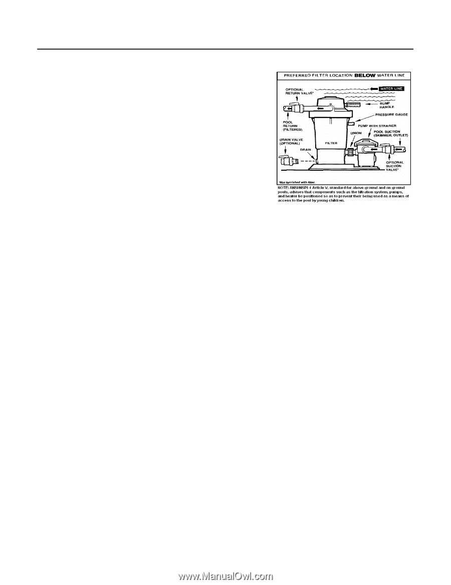
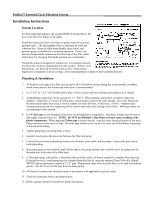
Perflex™ Extended Cycle Filtration System Installation Instructions System Location For best pump performance, the system MUST be located below the pool water line (See Figure to the right). Install the system on a firm, level base or pad to meet all local and national codes. The field supplied base or pad must be level and vibration-free. Keep the filter bump handle, drain outlet, and pressure gauge accessible for convenient operation. There is an alternate bump handle location on the other side of the filter outlet. Instructions for changing the handle position are covered later. Though the pump is designed for outdoor use, it is strongly advised to protect the electrical components from the weather. Select a welldrained area, one that will not flood when it rains. Pump motors require free circulation of air for cooling. Do not install pump in a damp or non-ventilated location. Plumbing & Installation 1. To facilitate servicing of the filter system and to allow for indoor storage during the winter months, installing union connections at the suction and outlet ports is recommended. 2. Use 1-1/4" or 1-1/2" I.D. flexible plastic pipe, or hose, joined with insert fittings and stainless steel clamps. 3. All plumbing connections on the system are 1 ½" N.P.T. When making connections, use plastic male-end adapters. Apply three (3) turns of Teflon tape or plastic pipe sealant to the male threads. Screw the fitting into the thread hand-tight; then using a wrench, tighten one more full turn, if necessary. (NOTE: Adapters have varying tolerances and over-tightening with a wrench may only cause damage to the filter.) Ball type valves are recommended where needed. 4. Use Teflon tape to seal threaded connections on molded plastic components. All plastic fittings must be new or thoroughly cleaned before use. NOTE: Do NOT use Plumber's Pipe Dope as it may cause cracking of the plastic components. When applying Teflon tape to plastic threads, wrap the entire threaded portion of the male fitting with one to two layers of tape. Wind the tape clockwise as you face the open end of the fitting, beginning at the end of the fitting. 5. Tighten pump base mounting bolts, if loose. 6. Securely hand tighten the union nut between the filter and pump. 7. Connect the pool suction plumbing between the skimmer, pool outlet, and the pump. Connect the pool return (inlet) plumbing. 8. If pressure gauge is not installed, apply Teflon tape to the gauge threads, and carefully screw the gauge into the threaded hole in the side of the filter body. 9. A filter drain plug, with gasket, is furnished with each filter and is all that is needed for complete filter draining. If desired however, drain piping may be extended from the filter by using the optional Drain Valve Kit (Model SP0723) and an appropriate length of 1-1/2" pipe. Piping must slope away from the filter so the tank can drain by gravity. DO NOT use roll-flat type hose for drain piping. 10. All electrical connections should be made in accordance with applicable electrical codes. 11. Check for joint leaks before operating system. 12. Refer to pump instruction booklet for pump information.
-
 1
1 -
 2
2 -
 3
3 -
 4
4 -
 5
5 -
 6
6 -
 7
7 -
 8
8 -
 9
9 -
 10
10 -
 11
11 -
12
 |
 |