Hayward Power-Flo LX Owners Manual - Page 4
Installation Instructions - pumps and motors
 |
View all Hayward Power-Flo LX manuals
Add to My Manuals
Save this manual to your list of manuals |
Page 4 highlights
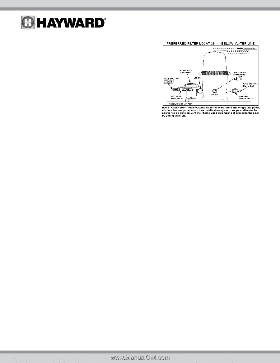
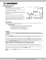
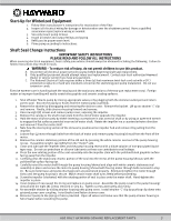
Installation Instructions Pump Location The PowerFlo LX™ and EP series pumps MUST be installed below the pool water line (see Figure to right). Self-priming PowerFlo II™ pumps may be installed up to four (4) feet above the pool water line. Install pump on a firm, level base or pad to meet all local and national codes. The field supplied base or pad must be level and vibration-free. Pump motors require free circulation of air for cooling. Do NOT install pump in a damp or non-ventilated location. Though the pump is designed for outdoor use, it is strongly advised to protect the electrical components from the weather. Select a well-drained area, one that will not flood when it rains. Pump Mounting Fasten pump to base or pad with screws or bolts to further reduce vibration and stress on pipe or hose joints. The base MUST be solid - level - rigid - vibration free. Pump mount must: Allow pump inlet height to be as close to water level as possible. Allow use of short, direct suction pipe (to reduce friction losses). Allow for ball valves in suction and outlet piping. Be protected from excess moisture and flooding. Allow adequate access for servicing pump and piping. Plumbing Use TFE tape to seal threaded connections on molded plastic components. All plastic fittings must be new or thoroughly cleaned before use. NOTE: Do NOT use Plumber's Pipe Dope as it may cause cracking of the plastic components. When applying TFE tape to plastic threads, wrap the entire threaded portion of the male fitting with one to two layers of tape. Wind the tape clockwise as you face the open end of the fitting, beginning at the end of the fitting. The pump suction and outlet ports have molded-in thread stops. Do NOT attempt to force hose connector fitting past this stop. It is only necessary to tighten fittings enough to prevent leakage. Tighten fitting by hand and then use a tool to engage fitting an additional 1 ½ turns. Use care when using TFE tape as friction is reduced considerably; do NOT over-tighten fitting or you may cause damage. If leaks occur, remove connector, clean off old Teflon tape, re-wrap with one to two additional layers of TFE tape, and re-install connector. Piping - Flexible Hose, PVC, or Reinforced Hose are all acceptable piping methods For pump outlet use 1-1/2" PVC pipe or reinforced hose. For pump suction on ALL models, use 1-1/2" reinforced hose. Increase size if a long run is needed. For pipe larger than port, use reducing fitting in strainer port. To avoid pump strain, support suction and outlet independently. Place supports near pump. To avoid strain left by a gap at last connection, start all piping at pump and run pipe AWAY from pump. NEVER use suction pipe SMALLER than pump suction connections. Suction pipe inlet must be lower than pump inlet port. USE ONLY HAYWARD GENUINE REPLACEMENT PARTS 4
-
 1
1 -
 2
2 -
 3
3 -
 4
4 -
 5
5 -
 6
6 -
 7
7 -
 8
8 -
 9
9 -
 10
10 -
11
-
12
 |
 |