HealthRider 875p Treadmill Uk Manual - Page 7
Set the Console Base 38 on the Right Upright 55
 |
View all HealthRider 875p Treadmill manuals
Add to My Manuals
Save this manual to your list of manuals |
Page 7 highlights
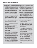
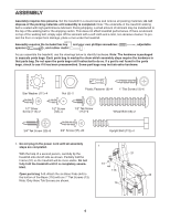
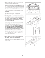
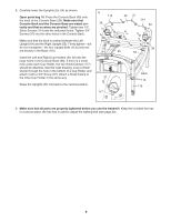
2. Identify the Right and Left Uprights (55, 64); the Left Upright has two small holes near the square post. Hold the Right Upright (55) near the Base (116), and orient the Right Upright as shown. Make sure that the Right Upright bends in the direction shown. Straighten the Wire Harness (49), and feed it into the lower end of the Right Upright and out of the upper end. Make sure that the Wire harness is not pinched. Hand tighten two Upright Bolts (112) with Star Washers (111) into the bottom of the Base (116) and the lower end of the Right Upright. Attach the Left Upright (64) as described above. Note: There is not a wire harness on the left side. 2 112 111 49 116 Holes 55 Bend 64 112 111 3. With the help of a second person, carefully tip the treadmill back down so that the Uprights (55, 64 [not shown]) are vertical. Make sure that the end of the Wire Harness (49) does not fall into the Right Upright. Set the Console Base (38) on the Right Upright (55) as shown. Check the pins in the connector on the Wire Harness and make sure that they are straight. Connect the Wire Harness to the indicated connector on the back of the Console Base. Make sure to insert the connectors properly (see the inset drawing). The connectors should slide together easily and snap into place. If the connectors do not slide together easily and snap into place, turn one connector and try again. Insert the included plastic tie through the small hole in the Right Upright (55) and around the Wire Harness (49) as shown. Connect the two indicated ground wires. 3 38 Tie 55 49 Ground Wires 49 4. Open parts bag 4-5. Loosely thread a 1/2" Tek Screw (113) into the left side of the Crossbar (46) and the Left Upright (64). Note: The Tek Screw may be preassembled in the Left Upright. Attach the Latch Assembly (32) to the Left Upright (64) with two 3/4" Tek Screws (35). 4 113 (Leave loose) 46 35 32 64 7
-
 1
1 -
 2
2 -
 3
3 -
 4
4 -
 5
5 -
 6
6 -
 7
7 -
 8
8 -
 9
9 -
 10
10 -
 11
11 -
 12
12 -
13
-
14
-
15
-
16
-
17
-
18
-
19
-
20
-
21
-
22
-
23
-
24
-
25
-
26
-
27
-
28
-
29
-
30
-
31
-
32
-
33
-
34
-
35
 |
 |
