HealthRider C515e Elliptical English Manual - Page 7
Handlebar Leg with two M8 x 45mm Button Bolts 50
 |
View all HealthRider C515e Elliptical manuals
Add to My Manuals
Save this manual to your list of manuals |
Page 7 highlights
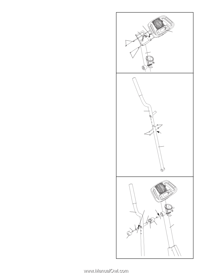
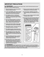
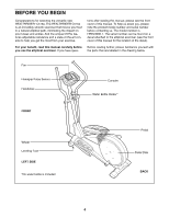
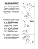
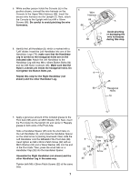
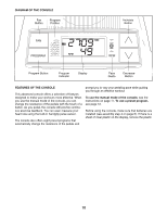
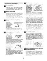
5. While another person holds the Console (5) in the position shown, connect the wire harness on the Console to the Upper Wire Harness (86). Insert the excess wire harness into the Upright (2). Next, attach the Console to the Upright with four M4 x 16mm Screws (66). Be careful to avoid pinching the wire harnesses. 5 Wire Harness 86 5 66 Avoid pinching 2 or damaging the wire harnesses 66 during this step. 6. Identify the Left Handlebar (9), which is marked with a 6 "Left" sticker. Insert the Left Handlebar into one of the Handlebar Legs (79); make sure that the Handlebar Leg is turned so the hexagonal holes are on the indicated side. Attach the Left Handlebar to the Handlebar Leg with two M8 x 45mm Button Bolts (50) and two M8 Nylon Locknuts (46). Make sure that the Nylon Locknuts are inside the hexagonal holes. Do not tighten the Button Bolts yet. Repeat this step for the Right Handlebar (not shown) and the other Handlebar Leg. 9 46 50 Hexagonal Holes 79 7. Apply a generous amount of the included grease to the 7 Pivot Axle (38) and to an M8.5 Washer (53). Next, insert the Pivot Axle into the Upright (2) and center it. Reapply grease to both ends of the Pivot Axle. Slide a Handlebar Spacer (25) onto the short tube on the Left Handlebar (9), and rotate the Handlebar Spacer so the small arrow is pointing downward. Next, slide the Left Handlebar onto the left end of the Pivot Axle (38). Hand tighten an M8 x 25mm Patch Screw (22) with an M8.5 Washer (53) and a Wave Washer (95) into the end of the Pivot Axle. Then, press the small tabs on a Handlebar Cap (23) into the Handlebar Spacer. Assemble the Right Handlebar (not shown) and the other Handlebar Leg in the same way. Grease 9 Tube 53 38 2 22 25 Arrow 95 23 Tighten both M8 x 25mm Patch Screws (22) at the same time. 7
-
 1
1 -
 2
2 -
 3
3 -
 4
4 -
 5
5 -
 6
6 -
 7
7 -
 8
8 -
 9
9 -
 10
10 -
 11
11 -
 12
12 -
13
-
14
-
15
-
16
-
17
-
18
-
19
-
20
 |
 |