HealthRider C860e Elliptical Canadian English Manual - Page 6
M10 x 112mm Carriage Bolts 34 and two M10 Nylon
 |
View all HealthRider C860e Elliptical manuals
Add to My Manuals
Save this manual to your list of manuals |
Page 6 highlights
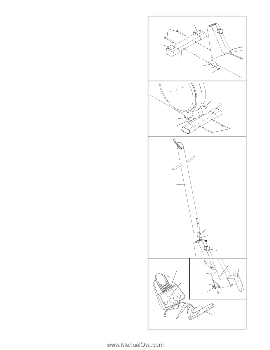
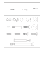
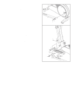
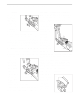
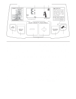
1. Identify the Front Stabilizer (3), which has Wheels (32) attached to it. While another person lifts the front of the Frame (1), attach the Front Stabilizer to the Frame with two M10 x 112mm Carriage Bolts (34) and two M10 Nylon Locknuts (29). Make sure that the Front Stabilizer is turned so the Wheels are not touching the floor. 2. While another person lifts the back of the Frame (1), attach the Rear Stabilizer (4) to the Frame with two M10 x 112mm Carriage Bolts (34) and two M10 Nylon Locknuts (29). 1 34 32 2 32 3 1 29 29 4 29 1 3. While another person holds the Upright (2) in the posi- 3 tion shown, connect the Upper Wire Harness (86) to the Lower Wire Harness (87). Carefully pull the upper end of the Upper Wire Harness to remove any slack. While holding the upper end of the Upper Wire Harness, insert the Upright into the Frame (1). Do not pinch the Wire Harnesses. Next, turn the Upright Knob (91) counterclockwise sev- eral turns. Pull the Knob, slide the Upright (2) down 2 until the Knob is aligned with one of the four adjust- ment holes, and then release the Knob. Do not tighten the Knob yet. 34 Make sure the Wire Harnesses (86, 87) do not get pinched and damaged during this step. 4. Connect the wire harness on the Handgrip Pulse Sensor (81) to the indicated wire harness on the Console (5). Insert both wire harnesses into the opening in the bottom of the Console. Refer to the inset drawing. Insert the metal tube on the Handgrip Pulse Sensor (81) into the metal bracket inside the Console (5) as shown. Be careful not to pinch the wire harnesses. Align the holes in the metal tube with the holes in the metal bracket, and tighten two M4 x 16mm Screws (66) into the indicated holes. Snap the bookrack onto the Console (5) in the location shown. 6 86 87 1 91 4 Bookrack 66 5 Bracket Tube 5 81 66 81 Wire Harnesses
-
 1
1 -
 2
2 -
 3
3 -
 4
4 -
 5
5 -
 6
6 -
 7
7 -
 8
8 -
 9
9 -
 10
10 -
 11
11 -
 12
12 -
13
-
14
-
15
-
16
-
17
-
18
-
19
-
20
-
21
-
22
-
23
-
24
 |
 |