HealthRider H85t Treadmill English Manual - Page 11
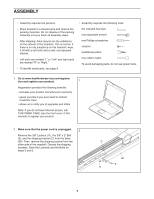
Aged When You Turn On The Power.
 |
View all HealthRider H85t Treadmill manuals
Add to My Manuals
Save this manual to your list of manuals |
Page 11 highlights
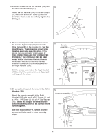
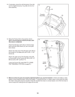
10. Insert the bracket on the Left Handrail (106) into 10 the top of the Left Upright (77). Attach the Left Handrail (106) to the Left Upright (77) with three 5/16" x 3/4" Bolts (4) and three 5/16" Star Washers (9); do not fully tighten the Bolts yet. 106 77 4 9 4 11. Have a second person hold the console assembly near the Right Upright (79). Connect the Wire Harness (86) to the console wire. See the inset drawing. The connectors should slide together easily and snap into place. If they do not, turn one connector and try again. IF THE CONNECTORS ARE NOT CONNECTED PROPERLY, THE CONSOLE MAY BE DAMAGED WHEN YOU TURN ON THE POWER. Remove the wire tie from the Wire Harness. Insert the connectors and the excess wire into the Right Handrail (105). Set the console assembly on the Right Handrail (105) and Left Handrail (not shown). Be careful not to pinch the wires. 11 Console Assembly Console Wire 105 86 Wire Tie 79 Console Wire 86 12. Be careful not to pinch the wires in the Right Handrail (105). Attach the console assembly to the Right Handrail (105) with two #8 x 3/4" Screws (1) and a 1/4" x 1 1/4" Screw (6) with a 1/4" Star Washer (10). Repeat this step on the left side of the console assembly. Start all six Screws before tightening them. See step 5 and steps 7–-9. Tighten all of the screws and bolts used in these assembly steps. 12 Console Assembly 105 1 10 6 11
-
 1
1 -
2
-
3
-
4
-
5
-
 6
6 -
 7
7 -
 8
8 -
 9
9 -
 10
10 -
 11
11 -
 12
12 -
 13
13 -
 14
14 -
 15
15 -
 16
16 -
17
-
18
-
19
-
20
-
21
-
22
-
23
-
24
-
25
-
26
-
27
-
28
-
29
-
30
-
31
-
32
 |
 |
