HP 14-bs100 Maintenance and Service Guide
HP 14-bs100 Manual
 |
View all HP 14-bs100 manuals
Add to My Manuals
Save this manual to your list of manuals |
HP 14-bs100 manual content summary:
- HP 14-bs100 | Maintenance and Service Guide - Page 1
HP 14 Laptop PC (Intel) HP 14g Laptop PC HP 14q Laptop PC Maintenance and Service Guide - HP 14-bs100 | Maintenance and Service Guide - Page 2
://www.support.hp.com. The information contained herein is subject to change without notice. The only warranties for HP products and services are Edition: April 2017 Document Part Number: 924970-003 Product notice This guide describes features that are common to most models. Some features may not - HP 14-bs100 | Maintenance and Service Guide - Page 3
Safety warning notice WARNING! To reduce the possibility of heat-related injuries or of overheating the device, do not place the device directly on your lap or obstruct the device air vents. Use the device only on a hard, flat surface. Do not allow another hard surface, such as an adjoining optional - HP 14-bs100 | Maintenance and Service Guide - Page 4
iv Safety warning notice - HP 14-bs100 | Maintenance and Service Guide - Page 5
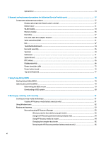
devices ...23 Cables ...24 Miscellaneous parts ...25 4 Removal and replacement procedures preliminary requirements 27 Tools required ...27 Service considerations ...27 Plastic parts ...27 Cables and connectors ...27 Drive handling ...28 Grounding guidelines ...28 Electrostatic discharge damage - HP 14-bs100 | Maintenance and Service Guide - Page 6
Optical drive ...34 6 Removal and replacement procedures for Authorized Service Provider parts 37 Component replacement procedures ...37 Display subcomponents (bezel, panel, camera 37 Bottom cover ...41 WLAN module ...43 Memory module ...45 Hard drive ...47 M.2 - HP 14-bs100 | Maintenance and Service Guide - Page 7
9 Using HP PC Hardware Diagnostics (UEFI) ...87 Downloading HP PC Hardware Diagnostics (UEFI) to a USB device 87 10 Specifications ...89 Computer specifications ...89 35.6-cm (14.0-in) display specifications ...90 Hard drive specifications ...91 M.2 solid-state drive specifications ...92 DVD±RW - HP 14-bs100 | Maintenance and Service Guide - Page 8
viii - HP 14-bs100 | Maintenance and Service Guide - Page 9
1 Product description Category Product name Processor Graphics Description HP 14 Laptop PC (Intel) * Model numbers: 14-bs0xx, 14-bs1xx, 14-bs2xx, 14-bs5xx, 14-bs6xx HP 14g Laptop PC * Model numbers: 14g-br0xx, 14g-br1xx, 14g-br2xx HP 14q Laptop PC * Model numbers: 14q-bu0xx, 14q-bu1xx, 14q-bu2xx - HP 14-bs100 | Maintenance and Service Guide - Page 10
Radeon™ M520 R17M-M1-30 with 4096 MB of dedicated video memory AMD Radeon M520 R17M-M1-30 with 2048 MB of dedicated video memory Support HD Decode, DX12, and HDMI 35.6-cm (14.0-in), high-definition (HD), white light-emitting diode (WLED), SVA, BrightView (1366×768) display, slim-flat 3.0 mm - HP 14-bs100 | Maintenance and Service Guide - Page 11
HDD eMMC configuration: ● 128 GB ● 64 GB ● 32 GB Fixed, serial ATA, 9.0-mm tray load DVD+/-RW Double-Layer writer Supports zero power optical drive Supports M-disc Supports configuration without optical drive HP TrueVision HD camera - activity LED, USB 2.0, HD BSI sensor, f2.0, 720p by 30 frames per - HP 14-bs100 | Maintenance and Service Guide - Page 12
/line in combo jack Full-size textured, island style keyboard TouchPad with multi-touch gestures enabled TouchPad taps enabled by default TouchPad supports Modern Trackpad Gestures AC adapters 65-W EM 65-W (models with discrete graphics only) 45-W (models with UMA graphics only) 1 meter power cord - HP 14-bs100 | Maintenance and Service Guide - Page 13
Category Security Operating system Service Description 3-cell, 31-Whr Li-ion battery fTPM 2.0 Kensington Security Lock Preinstalled Windows 10 Windows 10 Professional For Developed Market (ML): Windows 10 Home ML - HP 14-bs100 | Maintenance and Service Guide - Page 14
Category Description AC adapter Battery Optical drive 6 Chapter 1 Product description - HP 14-bs100 | Maintenance and Service Guide - Page 15
2 Getting to know your computer Your computer features top-rated components. This chapter provides details about your components, where they're located, and how they work. Right side Component (1) Power light (2) Drive light Description ● On: The computer is on. ● Blinking: The computer is in - HP 14-bs100 | Maintenance and Service Guide - Page 16
, or a headset. For additional safety information, refer to the Regulatory, Safety, and Environmental Notices. To access this guide: ▲ Select the Start button, select HP Help and Support, and then select HP Documentation. NOTE: When a device is connected to the jack, the computer speakers are - HP 14-bs100 | Maintenance and Service Guide - Page 17
obstructions. For wireless regulatory notices, see the section of the Regulatory, Safety, and Environmental Notices that applies to your country or region. To access this guide: ▲ Select the Start button, select HP Help and Support, and then select HP Documentation. Display 9 - HP 14-bs100 | Maintenance and Service Guide - Page 18
Keyboard area TouchPad Component (1) (2) (3) TouchPad zone Left TouchPad button Right TouchPad button Description Reads your finger gestures to move the pointer or activate items on the screen. Functions like the left button on an external mouse. Functions like the right button on an external - HP 14-bs100 | Maintenance and Service Guide - Page 19
Lights Component (1) (2) Caps lock light Mute light Description On: Caps lock is on, which switches the key input to all capital letters. ● Amber: Computer sound is off. ● Off: Computer sound is on. Keyboard area 11 - HP 14-bs100 | Maintenance and Service Guide - Page 20
Button Component Power button Description ● When the computer is off, press the button to turn on the computer. ● When the computer is on, press the button briefly to initiate Sleep. ● When the computer is in the Sleep state, press the button briefly to exit Sleep. ● When the computer is in - HP 14-bs100 | Maintenance and Service Guide - Page 21
Special keys Component (1) (2) (3) esc key fn key Windows key (4) Action keys Description Displays system information when pressed in combination with the fn key. Executes specific functions when pressed in combination with another key. Opens the Start menu. NOTE: Pressing the Windows key again - HP 14-bs100 | Maintenance and Service Guide - Page 22
on your product, see Special keys on page 13. ▲ To use an action key, press and hold the key. Icon Description Opens the HP Support Assistant app. Decreases the screen brightness incrementally as long as you hold down the key. Increases the screen brightness incrementally as long as you hold - HP 14-bs100 | Maintenance and Service Guide - Page 23
Bottom Component (1) (2) (3) (4) (5) Battery lock Description Locks the battery in the battery bay. Battery bay Battery release latch Holds the battery. Releases the battery. Speakers (2) Vent Produce sound. Enables airflow to cool internal components. NOTE: The computer fan starts up - HP 14-bs100 | Maintenance and Service Guide - Page 24
provide information you may need when you troubleshoot system problems or travel internationally with the computer. IMPORTANT: Check the following locations for the labels described in this section: the bottom of the computer, inside the battery bay, under the service door, or on the back of the - HP 14-bs100 | Maintenance and Service Guide - Page 25
Computer major components NOTE: HP continually improves and changes product parts. For complete and current information on supported parts for your computer, go to http://partsurfer.hp.com, select your country or region, and then follow the on-screen instructions. Computer major components 17 - HP 14-bs100 | Maintenance and Service Guide - Page 26
Item (1) (2) (3) (4) (5) (6) (7) (8) (9) (10) (11) (12) Component Display assembly NOTE: For display assembly spare part information, see Display assembly subcomponents on page 21. Top cover/keyboard NOTE: For a detailed list of keyboard country codes, see Top cover/keyboard on page 77. Jet black - HP 14-bs100 | Maintenance and Service Guide - Page 27
Item Component ● Intel Core i5-7200U processor and 4 GB of discrete graphics memory ● Intel Core i5-7200U processor and 2 GB of discrete graphics memory ● Intel Core i3-7020U processor and 2 GB of discrete graphics memory ● Intel Core i3-6006U processor and 2 GB of discrete graphics memory For - HP 14-bs100 | Maintenance and Service Guide - Page 28
Item (16) (17) (18) (19) (20) (21) (22) Component Fan Heat sink assembly (includes replacement thermal materials) For use in models with discrete graphics memory For use in models with UMA graphics memory and Intel Core processors For use in models with UMA graphics and Intel Pentium or Celeron - HP 14-bs100 | Maintenance and Service Guide - Page 29
Display assembly subcomponents Item Component (1) Display bezel (2) Raw display panel (35.6-cm [14.0-in]) FHD, anti glare FHD, BrightView HD, anti glare HD, BrightView (3) Camera/microphone module HD VGA Spare part number 925335-001 821816-007 847660-006 916357-002 847664-006 919471- - HP 14-bs100 | Maintenance and Service Guide - Page 30
Item (4) (5) (6) (7) (8) Component Hinge covers Right, jack black Left, jack black Right, jack black Left, jack black Right, textured black Left, textured black Hinge Kit (left and right) Display cable (includes display panel cable and camera/microphone cable) Antenna (includes wireless antenna - HP 14-bs100 | Maintenance and Service Guide - Page 31
Mass storage devices Item Component (1) Hard drive, SATA; does not include brackets, connector board, or cable): 1-TB, 5400-rpm 500-GB, 5400-rpm (2) Hard drive bracket eMMC module, 128 GB (not illustrated) (3) Solid-state drive, M.2 NOTE: Mylar for use with solid-state drives is - HP 14-bs100 | Maintenance and Service Guide - Page 32
Item (6) (7) Component Optical drive bezel Jack black Snow white Smoke gray Marine blue Pike/natural silver Silk gold Empress red Optical drive bracket Cables Spare part number 925336-001 925337-001 925338-001 925339-001 925340-001 925341-001 925658-001 925353-001 Item (1) (2) (3) (4) Component - HP 14-bs100 | Maintenance and Service Guide - Page 33
Miscellaneous parts Component HP Smart AC adapter (4.5 mm, non-PFC): 90-W 65-W 65-W, for use in Argentina 65-W, EM, for use in India and the People's Republic of China 45-W 45-W, for use in Argentina Power cord: For use in Argentina For use in Australia For use in Denmark For use in Europe For use - HP 14-bs100 | Maintenance and Service Guide - Page 34
26 Chapter 3 Illustrated parts catalog - HP 14-bs100 | Maintenance and Service Guide - Page 35
plastic parts. Use care when handling the plastic parts. Apply pressure only at the points designated in the maintenance instructions. Cables and connectors CAUTION: When servicing the computer, be sure that cables are placed in their proper locations during the reassembly process. Improper cable - HP 14-bs100 | Maintenance and Service Guide - Page 36
Drive handling CAUTION: Drives are fragile components that must be handled with care. To prevent damage to the computer, damage to a drive, or loss of information, observe these precautions: Before removing or inserting a hard drive, shut down the computer. If you are unsure whether the computer is - HP 14-bs100 | Maintenance and Service Guide - Page 37
material. ● Use a wrist strap connected to a properly grounded work surface and use properly grounded tools and equipment. ● Use conductive field service tools, such as cutters, screwdrivers, and vacuums. ● When fixtures must directly contact dissipative surfaces, use fixtures made only of static - HP 14-bs100 | Maintenance and Service Guide - Page 38
with ground cords of one megohm resistance ● Static-dissipative tables or floor mats with hard ties to the ground ● Field service kits ● Static awareness labels ● Material-handling packages ● Nonconductive plastic bags, tubes, or boxes ● Metal tote boxes ● Electrostatic voltage levels and - HP 14-bs100 | Maintenance and Service Guide - Page 39
on supported parts for your computer, go to http://partsurfer.hp.com, select your country or region, and then follow the on-screen instructions. many as 2 screws that must be removed, replaced, or loosened when servicing Customer SelfRepair parts. Make special note of each screw size and location - HP 14-bs100 | Maintenance and Service Guide - Page 40
Battery Description 4-cell, 41-Whr, 2.8-Ah Li-ion battery 3-cell, 31-Whr, 2.8-Ah Li-ion battery Spare part number 919701-850 919700-850 Before disassembling the computer, follow these steps: 1. Shut down the computer. If you are unsure whether the computer is off or in Hibernation, turn the - HP 14-bs100 | Maintenance and Service Guide - Page 41
To replace the battery, align the battery so it is parallel to the rear of the computer, and then push the battery into the battery bay until it snaps into place (1). Slide the battery lock latch (2) to lock the battery. Component replacement procedures 33 - HP 14-bs100 | Maintenance and Service Guide - Page 42
Optical drive Description DVD+/-RW Double-Layer SuperMulti Drive Optical drive bracket Optical drive bezel Snow white Smoke gray Marine blue Pike/natural silver Silk gold Empress red Jack black Spare part number 920417-001 925353-001 925337-001 925338-001 925339-001 925340-001 925341-001 925658-001 - HP 14-bs100 | Maintenance and Service Guide - Page 43
3. If it is necessary to remove the optical drive bezel, insert a paper clip into the release hole (1) to disengage the bezel. Press the tab (2) to release the bezel from the drive. Rotate the side of the bezel (3), and the remove it (4). 4. If it is necessary to replace the bracket on the rear of - HP 14-bs100 | Maintenance and Service Guide - Page 44
36 Chapter 5 Removal and replacement procedures for Customer Self-Repair parts - HP 14-bs100 | Maintenance and Service Guide - Page 45
hp.com, select your country or region, and then follow the on-screen instructions. Component replacement procedures NOTE: Details about your computer, including model, serial number, product key, and length of warranty, are on the service tag at the bottom of your computer. See Labels on page 16 for - HP 14-bs100 | Maintenance and Service Guide - Page 46
that secures it to the display (1). c. Disconnect the cable (2) from the module. 4. To remove the display panel: 38 Chapter 6 Removal and replacement procedures for Authorized Service Provider parts - HP 14-bs100 | Maintenance and Service Guide - Page 47
a. Remove the four Phillips PM2.0×3.0 screws (1) that secure the display panel to the top of the enclosure. b. Rotate the display panel onto the keyboard (2) to gain access to the display cable connection on the back of the panel. c. On the back of the display panel, release the adhesive strip that - HP 14-bs100 | Maintenance and Service Guide - Page 48
d. Remove the display panel from the computer (2). Reverse this procedure to reassemble and install the display assembly components. 40 Chapter 6 Removal and replacement procedures for Authorized Service Provider parts - HP 14-bs100 | Maintenance and Service Guide - Page 49
Bottom cover Description Bottom cover for use in models with an optical drive: ● Pike/natural silver ● Silk gold ● Smoke gray ● Marine blue ● Snow white ● Empress red ● Jack black Bottom cover for use in models without an optical drive: ● Pike/natural silver ● Silk gold ● Smoke gray ● Marine blue ● - HP 14-bs100 | Maintenance and Service Guide - Page 50
tool (1) to pry the bottom cover from the computer (2). Reverse this procedure to install the bottom cover. 42 Chapter 6 Removal and replacement procedures for Authorized Service Provider parts - HP 14-bs100 | Maintenance and Service Guide - Page 51
in your country or region. If you replace the module and then receive a warning message, remove the module to restore device functionality, and then contact support. Before removing the WLAN module, follow these steps: 1. Shut down the computer. If you are unsure whether the computer is off or in - HP 14-bs100 | Maintenance and Service Guide - Page 52
the antenna connectors, as shown in the following illustration. Reverse this procedure to install the WLAN module. 44 Chapter 6 Removal and replacement procedures for Authorized Service Provider parts - HP 14-bs100 | Maintenance and Service Guide - Page 53
Memory module Description Memory module (PC3L-1600) For use in models with Intel Pentium and Celeron processors: 8-GB 4-GB 2-GB Memory module (PC4-2400) For use in models with 6th and 7th generation Intel Core processors: 8-GB 4-GB 2-GB Spare part number 693374-005 691740-005 691739-005 862398-855 - HP 14-bs100 | Maintenance and Service Guide - Page 54
2. Remove the memory module (2) by pulling it away from the slot at an angle. Reverse this procedure to install a memory module. 46 Chapter 6 Removal and replacement procedures for Authorized Service Provider parts - HP 14-bs100 | Maintenance and Service Guide - Page 55
Hard drive Three different SKUs related to storage are offered: ● Hard drive only ● M.2 solid-state drive only ● Hard drive and M.2 solid-state drive For hard drive only models, install the hard drive into hard drive bay. For solid-state drive only models, install the solid-state drive into the - HP 14-bs100 | Maintenance and Service Guide - Page 56
the hard drive, remove the four Phillips PM3.0×3.0 screws (1) that secure the bracket to the hard drive. 48 Chapter 6 Removal and replacement procedures for Authorized Service Provider parts - HP 14-bs100 | Maintenance and Service Guide - Page 57
4. Remove the hard drive bracket from the hard drive (2). Reverse this procedure to reassemble and install the hard drive. Component replacement procedures 49 - HP 14-bs100 | Maintenance and Service Guide - Page 58
out of the computer (3) Reverse this procedure to reassemble and install the solid-state drive adapter bracket. 50 Chapter 6 Removal and replacement procedures for Authorized Service Provider parts - HP 14-bs100 | Maintenance and Service Guide - Page 59
Solid-state drive (SSD) Description 512 GB solid-state drive 256 GB solid-state drive 128 GB solid-state drive Mylar for use with solid-state drives Spare part number 763008-015 865902-011 827560-040 930980-001 Before removing the solid-state drive, follow these steps: 1. Shut down the computer. - HP 14-bs100 | Maintenance and Service Guide - Page 60
PM2.0×5.0 screws (1) that secure the fan to the computer. 2. Disconnect the fan cable (2) from the system board. 52 Chapter 6 Removal and replacement procedures for Authorized Service Provider parts - HP 14-bs100 | Maintenance and Service Guide - Page 61
3. Remove the fan from the computer (3). Reverse this procedure to install the fan. Component replacement procedures 53 - HP 14-bs100 | Maintenance and Service Guide - Page 62
upward, and then remove it from the computer (3). Reverse this procedure to install the TouchPad button board. 54 Chapter 6 Removal and replacement procedures for Authorized Service Provider parts - HP 14-bs100 | Maintenance and Service Guide - Page 63
Heat sink assembly NOTE: The heat sink assembly spare part kit includes replacement thermal materials. Description Heat sink for use in models with UMA graphics and Intel Pentium or Celeron processors Heat sink for use in models with UMA graphics memory and Intel Core processors Heat sink for use - HP 14-bs100 | Maintenance and Service Guide - Page 64
Figure 6-1 Discrete graphics ● Discrete graphics Thermal paste is used on the processor and associated heat sink area (1)(2), as well as the graphics chip and associated heat sink area (3)(4). 4. 56 Chapter 6 Removal and replacement procedures for Authorized Service Provider parts - HP 14-bs100 | Maintenance and Service Guide - Page 65
Figure 6-2 UMA graphics ● UMA graphics Thermal paste is used on the heat sink (1) and the processor (2). 5. Component replacement procedures 57 - HP 14-bs100 | Maintenance and Service Guide - Page 66
Figure 6-3 UMA graphics (fanless) ● UMA graphics (fanless) Thermal paste is used on the heat sink (1) and the processor (2). Reverse this procedure to reassemble and install the heat sink assembly. 58 Chapter 6 Removal and replacement procedures for Authorized Service Provider parts - HP 14-bs100 | Maintenance and Service Guide - Page 67
Speakers Description Speakers (includes left and right speakers and cable) Spare part number 925376-001 Before removing the speakers, follow these steps: 1. Shut down the computer. If you are unsure whether the computer is off or in Hibernation, turn the computer on, and then shut it down through - HP 14-bs100 | Maintenance and Service Guide - Page 68
4. Lift up and remove the speakers from the computer (4). Reverse this procedure to install the speakers. 60 Chapter 6 Removal and replacement procedures for Authorized Service Provider parts - HP 14-bs100 | Maintenance and Service Guide - Page 69
USB board Description USB board for use in models with Intel Pentium or Celeron processors USB board for use in models with Intel Core processors USB board cable Spare part number 925363-001 925364-001 925343-001 Before removing the USB board, follow these steps: 1. Shut down the computer. If you - HP 14-bs100 | Maintenance and Service Guide - Page 70
, and then shut it down through the operating system. 2. Disconnect all external devices connected to the computer. 62 Chapter 6 Removal and replacement procedures for Authorized Service Provider parts - HP 14-bs100 | Maintenance and Service Guide - Page 71
3. Disconnect the power from the computer by first unplugging the power cord from the AC outlet and then unplugging the AC adapter from the computer. 4. Remove the battery (see Battery on page 32). 5. Remove the optical drive (see Optical drive on page 34), if installed. 6. Remove the bottom cover ( - HP 14-bs100 | Maintenance and Service Guide - Page 72
3. Rotate the side of the board upward (2), and then lift the system board out of the computer (3). Reverse this procedure to install the system board. 64 Chapter 6 Removal and replacement procedures for Authorized Service Provider parts - HP 14-bs100 | Maintenance and Service Guide - Page 73
RTC battery Description RTC battery Spare part number 746439-001 Before removing the RTC battery, follow these steps: 1. Shut down the computer. If you are unsure whether the computer is off or in Hibernation, turn the computer on, and then shut it down through the operating system. 2. Disconnect - HP 14-bs100 | Maintenance and Service Guide - Page 74
hinge) that secure the display assembly to the computer. 4. Lift the display to bend the hinges upward (2). 66 Chapter 6 Removal and replacement procedures for Authorized Service Provider parts - HP 14-bs100 | Maintenance and Service Guide - Page 75
5. Separate the display from the computer (3). If it is necessary to replace any of the display assembly subcomponents: 1. To remove the display bezel: a. Flex the inside of the top edge (1), the left and right edges (2), and the bottom edge (3) of the display bezel until the bezel disengages from - HP 14-bs100 | Maintenance and Service Guide - Page 76
: a. Remove the four Phillips PM2.0×3.0 screws (1) that secure the display panel to the top of the enclosure. 68 Chapter 6 Removal and replacement procedures for Authorized Service Provider parts - HP 14-bs100 | Maintenance and Service Guide - Page 77
b. Rotate the display panel onto the keyboard (2) to gain access to the display cable connection on the back of the panel. NOTE: The display will not be connected to the computer as shown in the following image. c. On the back of the display panel, release the adhesive strip that secures the display - HP 14-bs100 | Maintenance and Service Guide - Page 78
remove the display hinges: a. Pull either side of each hinge cap to disengage it from the enclosure (1). 70 Chapter 6 Removal and replacement procedures for Authorized Service Provider parts - HP 14-bs100 | Maintenance and Service Guide - Page 79
b. Remove the caps from the hinges (2). c. Remove the two Phillips PM2.0×3.0 screws (1), and then lift the top display hinge (2) off the display. d. Remove the three broadhead Phillips PM2.5×3.0 screws (1) and the PM2.0×3.0 screw (2) that secure each hinge to the display enclosure. Component - HP 14-bs100 | Maintenance and Service Guide - Page 80
e. Remove the display hinges (3). 5. To remove the wireless antennas an cables, release the cables from the clips built into the side of the display enclosure (1), and then remove the antennas and cables (2)(3). 72 Chapter 6 Removal and replacement procedures for Authorized Service Provider parts - HP 14-bs100 | Maintenance and Service Guide - Page 81
6. To remove the display/camera cable, remove the cable from the clips built into the side of the display enclosure (1), and then remove the cable from the display enclosure (2). Component replacement procedures 73 - HP 14-bs100 | Maintenance and Service Guide - Page 82
hardware) are transferred to the new enclosure. Reverse this procedure to reassemble and install the display assembly. 74 Chapter 6 Removal and replacement procedures for Authorized Service Provider parts - HP 14-bs100 | Maintenance and Service Guide - Page 83
Power connector cable Description Power connector cable Spare part number 938292-001 Before removing the power connector cable, follow these steps: 1. Shut down the computer. If you are unsure whether the computer is off or in Hibernation, turn the computer on, and then shut it down through the - HP 14-bs100 | Maintenance and Service Guide - Page 84
power button board from the computer (4). Reverse this procedure to install the power button board and cable. 76 Chapter 6 Removal and replacement procedures for Authorized Service Provider parts - HP 14-bs100 | Maintenance and Service Guide - Page 85
Top cover/keyboard The top cover/keyboard spare part remains after all other spare parts have been removed. The top cover/keyboard spare part kit includes the keyboard and keyboard cable. In this section, the first table provides the main spare part number for the top cover/keyboard. The second - HP 14-bs100 | Maintenance and Service Guide - Page 86
78 Chapter 6 Removal and replacement procedures for Authorized Service Provider parts - HP 14-bs100 | Maintenance and Service Guide - Page 87
information regarding installing and troubleshooting the file. Determining the options. ● HP Support Assistant 1. Type support in the taskbar search box, and then select the HP Support Assistant app. - and then follow the on-screen instructions. To check for later BIOS versions, see Downloading a - HP 14-bs100 | Maintenance and Service Guide - Page 88
in the taskbar search box, and then select the HP Support Assistant app. - or - Click the question mark icon in the taskbar. 2. Click Updates, and then click Check for updates and messages. 3. Follow the on-screen instructions. 4. At the download area, follow these steps: a. Identify the most - HP 14-bs100 | Maintenance and Service Guide - Page 89
Download Tool to create a bootable USB drive for your HP recovery media. Go to https://support.hp.com/us-en/document/c05115630?openCLC=true, select your country or region, and follow the on-screen instructions. Creating HP Recovery media (select products only) If possible, check for the presence of - HP 14-bs100 | Maintenance and Service Guide - Page 90
for your computer from HP. You can find contact information on the HP website. Go to http://www.hp.com/support, select your country or region, and follow the on-screen instructions. - Be sure that the computer is connected to AC power before you begin creating the recovery media. - The creation - HP 14-bs100 | Maintenance and Service Guide - Page 91
to access the Get help app. ● If you need to correct a problem with a preinstalled application or driver, use the Reinstall drivers and/or Reinstall drivers and/or applications, and then follow the on-screen instructions. ● If you want to recover the Windows partition to original factory - HP 14-bs100 | Maintenance and Service Guide - Page 92
Go to http://www.hp.com/support, select your country or region, and follow the on-screen instructions. IMPORTANT: HP Recovery Manager does select f11. 2. Select Troubleshoot from the boot options menu. 3. Select Recovery Manager, and then follow the on-screen instructions. Using HP Recovery media - HP 14-bs100 | Maintenance and Service Guide - Page 93
drive from which you want to boot. 4. Follow the on-screen instructions. Removing the HP Recovery partition (select products only) HP Recovery Manager The Remove Recovery Partition option is only available on products that support this function. Follow these steps to remove the HP Recovery partition - HP 14-bs100 | Maintenance and Service Guide - Page 94
86 Chapter 8 Backing up, restoring, and recovering - HP 14-bs100 | Maintenance and Service Guide - Page 95
This ID code can then be provided to support to help determine how to correct the problem. NOTE: To start diagnostics on a convertible the type of diagnostic test you want to run, and then follow the on-screen instructions. NOTE: If you need to stop a diagnostic test, press esc. Downloading HP - HP 14-bs100 | Maintenance and Service Guide - Page 96
operating system. 5. In the Diagnostic section, follow the on-screen instructions to select and download the UEFI version you want. Additional BIOS Diagnostics 3-in-1 USB key. This tool can be used by HP authorized service providers to recover systems that have failed due to a corrupted BIOS. For - HP 14-bs100 | Maintenance and Service Guide - Page 97
10 Specifications Computer specifications Metric U.S. Dimensions Depth 240.0 mm 9.45 in Width 340.0 mm 13.39 in Height 23.7 mm 0.93 in Weight HDD configurations, 3 cell battery 1853 g 4.09 lb HDD configurations, 4 cell battery 1900 g 4.19 lb eMMC configurations, 3 cell battery - HP 14-bs100 | Maintenance and Service Guide - Page 98
35.6-cm (14.0-in) display specifications Active diagonal size Resolution Surface treatment Brightness Viewing angle Backlight Graphics adapter Thickness Metric 35.6-cm 1366x768 (HD) 1920x1080 (FHD) BrightView Anti glare 220 nits SVA (HD displays) UWVA (FHD displays) WLED eDP 3.0 mm U.S. 14.0-in - HP 14-bs100 | Maintenance and Service Guide - Page 99
Operating temperature *1 GB = 1 billion bytes when referring to hard drive storage capacity. Actual accessible capacity is less. NOTE: Certain restrictions and exclusions apply. Contact technical support for details. Hard drive specifications 91 - HP 14-bs100 | Maintenance and Service Guide - Page 100
°F to 185°F) *1 GB = 1 billion bytes when referring to hard drive storage capacity. Actual accessible capacity is less. NOTE: Certain restrictions and exclusions apply. Contact technical support for details. 92 Chapter 10 Specifications - HP 14-bs100 | Maintenance and Service Guide - Page 101
DVD±RW SuperMulti DL Drive specifications Component Applicable disc Center hole diameter Disc diameter Standard disc Mini disc Disc thickness Track pitch Access time Random Full stroke Audio output level Cache buffer Data transfer rate 24X CD-ROM 8X DVD-ROM 24X CD-R 16X CD-RW 8X DVD+R 4X DVD+RW 8X - HP 14-bs100 | Maintenance and Service Guide - Page 102
94 Chapter 10 Specifications - HP 14-bs100 | Maintenance and Service Guide - Page 103
11 Power cord set requirements The wide-range input feature of the computer permits it to operate from any line voltage from 100 to 120 volts ac, or from 220 to 240 volts ac. The 3-conductor power cord set included with the computer meets the requirements for use in the country or region where the - HP 14-bs100 | Maintenance and Service Guide - Page 104
Requirements for specific countries and regions Country/region Accredited agency Applicable note number Argentina IRAM 1 Australia SAA 1 Austria OVE 1 Belgium CEBEC 1 Brazil ABNT 1 Canada CSA 2 Chile IMQ 1 Denmark DEMKO 1 Finland FIMKO 1 France UTE 1 Germany VDE 1 - HP 14-bs100 | Maintenance and Service Guide - Page 105
Country/region Accredited agency Applicable note number 3. The appliance coupler, flexible cord, and wall plug must bear a "T" mark and registration number in accordance with the Japanese Dentori Law. The flexible cord must be Type VCTF, 3-conductor, 0.75mm2 or 1.25mm2 conductor size. The wall - HP 14-bs100 | Maintenance and Service Guide - Page 106
98 Chapter 11 Power cord set requirements - HP 14-bs100 | Maintenance and Service Guide - Page 107
12 Recycling When a non-rechargeable or rechargeable battery has reached the end of its useful life, do not dispose of the battery in general household waste. Follow the local laws and regulations in your area for battery disposal. HP encourages customers to recycle used electronic hardware, HP - HP 14-bs100 | Maintenance and Service Guide - Page 108
100 Chapter 12 Recycling - HP 14-bs100 | Maintenance and Service Guide - Page 109
cover illustrated 20 removing 41 buttons left TouchPad 10 optical drive eject 7 power 12 right TouchPad 10 C cables illustrated 24 cables, service considerations 27 camera identifying 9 camera light, identifying 9 camera/microphone cable illustrated 22 removing 38, 68, 70 camera/microphone module - HP 14-bs100 | Maintenance and Service Guide - Page 110
Diagnostics (UEFI) using 87 HP Recovery Manager correcting boot problems 85 starting 84 HP Recovery media creating 81 recovery 84 HP 13 fn 13 Windows 13 L labels Bluetooth 16 regulatory 16 serial number 16 service 16 wireless certification 16 WLAN 16 latches battery release 15 lights AC adapter - HP 14-bs100 | Maintenance and Service Guide - Page 111
ports 4 power requirements 4 processor 1 product name 1 security 5 serviceability 5 video 3 wireless 3 product name 1 product name and number, computer 16 R recover options 83 recovery discs 82, 84 HP Recovery Manager 83 media 84 starting 84 supported discs 82 system 83 USB flash drive 84 using HP - HP 14-bs100 | Maintenance and Service Guide - Page 112
104 Index
-
 1
1 -
 2
2 -
 3
3 -
 4
4 -
 5
5 -
 6
6 -
 7
7 -
8
-
9
-
10
-
11
-
12
-
13
-
14
-
15
-
16
-
17
-
18
-
19
-
20
-
21
-
22
-
23
-
24
-
25
-
26
-
27
-
28
-
29
-
30
-
31
-
32
-
33
-
34
-
35
-
36
-
37
-
38
-
39
-
40
-
41
-
42
-
43
-
44
-
45
-
46
-
47
-
48
-
49
-
50
-
51
-
52
-
53
-
54
-
55
-
56
-
57
-
58
-
59
-
60
-
61
-
62
-
63
-
64
-
65
-
66
-
67
-
68
-
69
-
70
-
71
-
72
-
73
-
74
-
75
-
76
-
77
-
78
-
79
-
80
-
81
-
82
-
83
-
84
-
85
-
86
-
87
-
88
-
89
-
90
-
91
-
92
-
93
-
94
-
95
-
96
-
97
-
98
-
99
-
100
-
101
-
102
-
103
-
104
-
105
-
106
-
107
-
108
-
109
-
110
-
111
-
112
 |
 |

HP 14 Laptop PC (Intel)
HP 14g Laptop PC
HP 14q Laptop PC
Maintenance and Service Guide